I
..
:
I,.
[,;
:
..
.:
~{
·{
;~
:
The Z Axis Amplifier circuit determines the CRT
intensity and blanking. The Z Axis Amplifier circuit sums
the current inputs from the INTENSITY control, Vertical
Switching circuit (chopped blanking), Z Axis Logic circuit
(unblanking), and the external Z AXIS INPUT connector.
The
output
level
of the Z Axis Amplifier circuit controls
the trace intensity through the CRT Circuit. The CRT
circuit provides the voltages and contains the controls
necessary for operation of the cathode-ray tube.
The Power Supply circuit provides the low voltage
power necessary for operation of this instrument. This
voltage
is
distributed
to
all
of the circuits
in
the instrument
as
shown
by
the Power Distribution Diagram. The
Cali-
brator circuit produces a square-wave
output
with accurate
voltage and current amplitudes which can
be
used
to
check
the calibration of the instrument and the compensation of
probes. The CALIBRATOR current loop provides an
accurate current source for calibration of current measuring
probe systems.
S5
Circuit Description-465
CHANNEL
1 PREAMP
General
Input signals for vertical deflection on the CRT can
be
connected to the
CH
1
OR
X input connector.
In
the
X-Y
mode of operation the input signal connected
to
the
CH
1
OR
X connector provides the horizontal
(X
axis) deflection
(TIME/DIV switch set
to
X-Y, VERT
MODE
switch set to
CH
2
OR
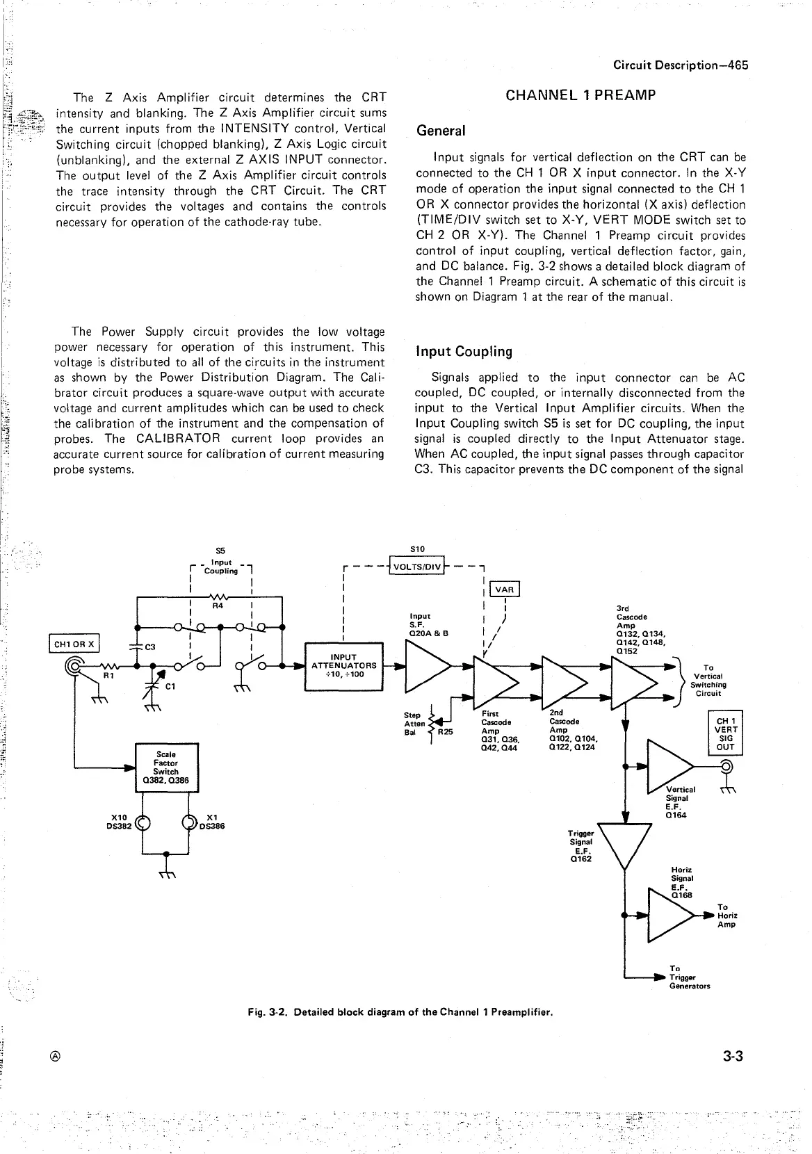
X-Y). The Channel 1 Preamp circuit provides
control of input coupling, vertical deflection factor, gain,
and
DC
balance. Fig. 3-2 shows a detailed block diagram of
the Channel 1 Preamp circuit. A schematic of this circuit
is
shown on Diagram 1 at the rear of the manual.
Input
Coupling
Signals applied
to
the input connector can
be
AC
coupled,
DC
coupled, or internally disconnected from the
input to the Vertical Input Amplifier circuits.
When
the
Input Coupling switch S5
is
set for
DC
coupling, the input
signal
is
coupled directly
to
the Input Attenuator stage.
When
AC
coupled, the input signal passes through capacitor
C3. This capacitor prevents the
DC
component
of the
signal
S10
r -
c!~~~~
9
- 7
I I
r - -
-1voLTS/DIV~
- - 7
I I
I
CH1
OR
XI
CJ
fi:'
Scale
Factor
Switch
Q382,Q386
X10
OS382
®
I I
R4
I
I
I
I
I
t
X1
OS386
I
1
ivARI
I I I
I I
I
Input
)
I
;;OA&B
I/
I 1/
INPUT
--.---11~
ATTENUATORS
+10, +100
y
First
Cascade
Amp
Q31,
036.
Q42, Q44
Fig. 3-2. Detailed block diagram
of
the
Channel 1 Preamplifier.
Trigger
Signal
E.F.
Q162
To
.__
__
Trigger
Generators
To
Horiz
Amp
3-3