I
I
Circuit Description-465
inverted with respect
to
the
input
signal. When
the
SLOPE
switch
is
set
to
the - position,
the
output
signal
at
pin 8
is
inverted with respect
to
the
input
signal
and
the
output
signal
at
pin 9
is
in
phase with
the
input
signal.
Tunnel Diode Driver
0650
and
0652
are
common-emitter
amplifier stages
that
provide
the
signal currents necessary
to
switch
the
triggering tunnel diodes.
CR650
and
CR652
are
4.7
mA
tunnel diodes. Quiescently (i.e.,
after
the
sweep holdoff
period has passed,
but
before triggering),
CR650
and
CR652
are biased
into
their low voltage states.
0650
cannot
provide sufficient
current
to
switch
CR650
to
its
high voltage state.
0652,
however, can provide sufficient
current
to
bias
CR652
into
its high voltage state; when
0652
next
conduc:s
triggering signal
current,
the
anode
of
CR652 steps positive
to
an
approximate
+0.5 volt level.
Since
only
approximately
1
mA
of
current
is
required
to
maintain
CR652
in
its high voltage
state,
this makes
approximately
3 mA
of
current
additionally available with
which
to
switch CR650
to
its high voltage state. Thus,
the
next
time
0650
conducts
signal
current,
CR650 steps
to
its
high voltage state, sending a positive pulse
to
the
logic
circuit
to
initiate sweep action. A Trigger Sensitivity
adjustment
R655 adjusts
the
tunnel
diode bias
to
the
proper level
that
will
not
allow
CR650
to
be switched
to
its
high voltage
state
until
CR652
has been switched
to
its high
voltage
state.
At
the
end
of
the
sweep time and during
holdoff, a negative level
is
applied
to
the
anode
of
CR652,
thereby resetting both
CR650
and
CR652
to
their low
voltage states. The reset level remains during holdoff time •
to
ensure
that
a sweep gating signal will
not
be generated
..
until
the
sweep circuit has
returned
to
its quiescent state.
A
AND
B SWEEP
GENERATORS
General
The A and B Sweep Generators produce sawtooth
voltages which are amplified by
the
Horizontal Amplifier
circuit
to
provide horizontal deflection on
the
CRT. These
sawtooth
voltages are
produced
on
command
(trigger
pulses) from
the
Trigger
Generator
circuits. The Sweep
Generator circuits also
produce
gate waveforms
that
are
used by
the
Z Axis Logic
circuit
to
unblank
the
CRT during
sweep time, and by
the
Sweep Logic
circuit
to
terminate
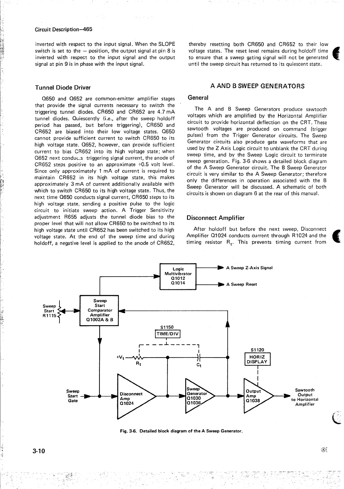
sweep generation. Fig. 3-6 shows a detailed block diagram
of
the
A Sweep Generator circuit.
The
B Sweep Generator
circuit
is
very similar
to
the
A Sweep
Generator;
therefore
only
the
differences in
operation
associated with the B
Sweep Generator will be discussed. A schematic
of
both
circuits
is
shown on diagram 6
at
the
rear
of
this manual.
Disconnect
Amplifier
After holdoff
but
before
the
next
sweep, Disconnect
Amplifier
01024
conducts
current
through
R1024 and
the
(·,
timing resistor Rt. This prevents timing
current
from
Logic
Multivibrator
01012
01014
1-----11
• A Sweep 2-Axis Signal
I-----~
A Sweep Reset
Sweep
Start
':>ill.__._.
R1115
Sweep
Sweep
Start
Comparator
Amplifier
01002A
& B
S1150
!TIME/DIV I
I
r----L-----,
I I
+Vt--'VV
1
1.,----------~1--------•
S.tart -11-....~~....,.111,1
Gate
Fig. 3-6. Detailed block diagram
of
the
A Sweep
Generator.
3-10
S1120
HORIZ
DISPLAY
Sawtooth
Output
to
Horizontal
Amplifier
®I