·.
~
-~
: :
Circuit Description-465
referenced
to
the
negative potential
of
the
CRT cathode.
The voltage difference across R1486 approximately equals
the voltage swing present
at
the junction of
CR
1482
and
CR1483. The control grid end
of
R1486
is
more negative
than the end connected
to
CR1488.
The amplitude
of
the
voltage swings present
at
the
junction of
CR
1482
and
CR1483
is
determined by
the
voltage levels established by
the
Z-Axis Amplifier and
the
CRT Bias adjust circuit.
CR1483 sets
the
limit
of
the positive excursion and
CR1482 sets
the
limit
of
the
negative excursion.
CALIBRATOR
General
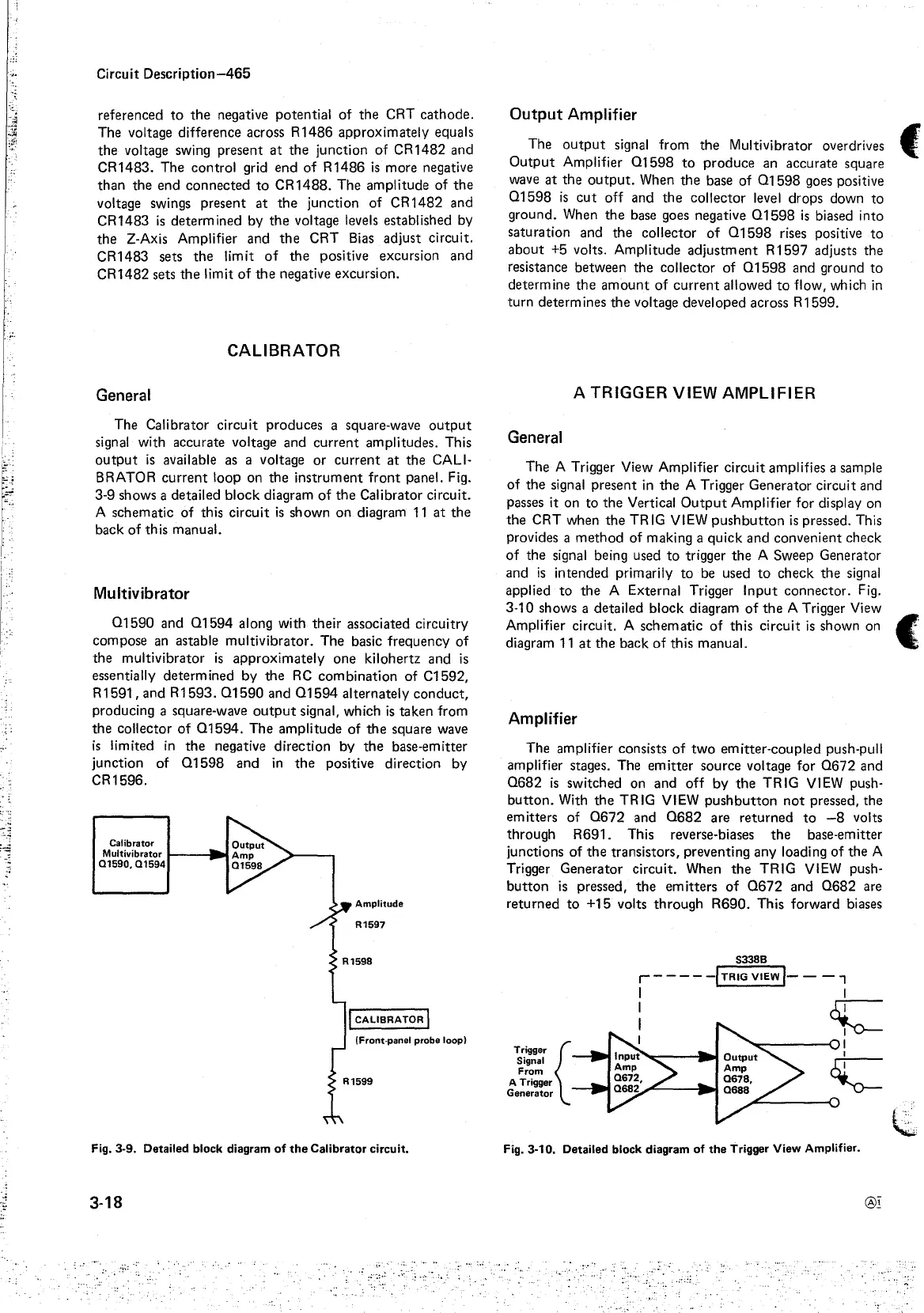
The Calibrator circuit produces a square-wave
output
signal with accurate voltage and
current
amplitudes. This
output
is
available as a voltage or
current
at
the CALI-
BRATOR
current
loop on
the
instrument
front
panel. Fig.
3-9 shows a detailed block diagram
of
the
Calibrator circuit.
A schematic
of
this circuit
is
shown
on
diagram
11
at
the
back of this manual.
Mu ltivibrator
01590
and
01594
along with their associated circuitry
compose an astable multivibrator. The basic frequency
of
the
multivibrator
is
approximately
one kilohertz and
is
essentially determined by
the
RC
combination
of C1592,
R1591,
and
R1593.
01590
and
01594
alternately
conduct,
producing a square-wave
output
signal, which
is
taken from
the
collector
of
01594.
The amplitude of
the
square wave
is
limited
in
the
negative direction by
the
base-emitter
junction of
01598
and
in
the
positive direction by
CR1596.
Calibrator
Multivibrator
t-------
01590,
Q1594
I
CALIBRATOR
I
(Front-panel probe
loop}
Fig. 3-9. Detailed block diagram
of
the
Calibrator circuit.
3-18
Output Amplifier
The
output
signal from
the
Multivibrator overdrives
Output
Amplifier
01598
to
produce
an accurate square
wave
at
the
output.
When
the
base
of
01598
goes positive
01598
is
cut
off and
the
collector level drops down
to
ground. When
the
base goes negative
01598
is
biased into
saturation and
the
collector
of
01598
rises positive
to
about
+5
volts. Amplitude
adjustment
R
1597
adjusts the
resistance between the collector of
01598
and ground
to
determine
the
amount
of
current
allowed
to
flow, which
in
turn
determines
the
voltage developed across R1599.
A
TRIGGER
VIEW
AMPLIFIER
General
The A Trigger View Amplifier circuit amplifies a sample
of
the
signal present
in
the
A Trigger Generator circuit and
passes it on
to
the
Vertical
Output
Amplifier for display on
the
CRT when
the
TRIG VIEW
pushbutton
is
pressed. This
provides a
method
of making a quick and convenient check
of
the
signal being used
to
trigger
the
A Sweep Generator
and
is
intended primarily
to
be used
to
check
the
signal
applied
to
the
A External Trigger
Input
connector. Fig.
f
3-10 shows a detailed block diagram
of
the
A Trigger View
Amplifier circuit. A schematic
of
this circuit
is
shown on
(:
diagram
11
at
the
back
of
this manual.
Amplifier
The amplifier consists
of
two
emitter-coupled push-pull
amplifier stages. The
emitter
source voltage for
0672
and
0682
is
switched on and
off
by
the
TRIG VIEW push-
button.
With
the
TRIG VIEW
pushbutton
not
pressed,
the
emitters of
0672
and
0682
are
returned
to
-8
volts
through R691. This reverse-biases
the
base-emitter
junctions
of
the
transistors, preventing any loading
of
the
A
Trigger Generator circuit. When
the
TRIG VIEW push-
button
is
pressed,
the
emitters
of
0672
and
0682
are
returned
to
+15 volts
through
R690. This forward biases
Trigger {
Signal
From
A Trigger
Generator
Fig. 3-10. Detailed block diagram
of
the
Trigger View Amplifier.