position, also adjusts
the
signal
currents
into
0122
and
0124
to provide uncalibrated deflection factors between
the
calibrated settings of
the
VOL
TS/DIV
switch. Variable
balance
adjustment
R120 adjusts for no baseline shift
of
a
CRT display when rotating
the
VAR
control.
Position
Centering
adjustment
R115
centers
the
range
of
control of
the
Channel 1 POSITION
control.
Third
Cascode
Amplifier
0132
and
0134,
in
conjunction
with
0304
and
0308
in
the Vertical Switching Circuit, form
the
Third
Cascode
Amplifier stage.
Thermistor
RT131 (between
the
emitters
of
0132
and
0134)
changes in value with changes
in
temperature.
This varies
the
gain of
the
Third
Cascode
Amplifier stage
to
compensate
for changes
in
total amplifier
gain
that
occur
with variations
in
operating
temperature.
The push-pull signals picked
off
in
the
emitters
of
0132
and
0134
are converted
to
a single-ended signal by
0142
and
0148.
This signal
is
amplified by common-base
amplifier stage
0152
and applied
to
the
bases
of
emitter
followers
0162
and
0164.
0164
provides
the
output
signal
to
the
CH
1
VERT
SIGNAL
OUT
connector
located
on
the
instrument
rear panel. The
output
signal
at
the
emitter
of
0162
is
used as
the
trigger signal source
in
the
CH
1
positions
of
the
Trigger SOURCE switches and as
the
signal
source for
emitter
follower
0168.
0168
provides
the
X-axis
signal from
the
Channel 1 Preamplifier
to
the
Horizontal
Amplifier
in
the
X-Y
mode
of
operation.
CR164, CR165,
CR
166,
and
CR
167
protect
the
emitter
circuit
of
0164
in
the
event
large voltage levels are accidentally
connected
to
the
CH
1
VERT
SIGNAL
OUT
connector.
R155 adjusts
the
DC
level
of
the
CH
1 trigger
source
signal.
S60
Circuit Description-465
CHANNEL 2 PREAMP
General
The Channel 2 Preamp
circuit
is
basically
the
same as
the
Channel 1 Preamp. Only
the
specific differences between
the
two
circuits are described here. Portions
of
this circuit
not
described
in
the
following
description
operate
in
the
same
manner
as for
the
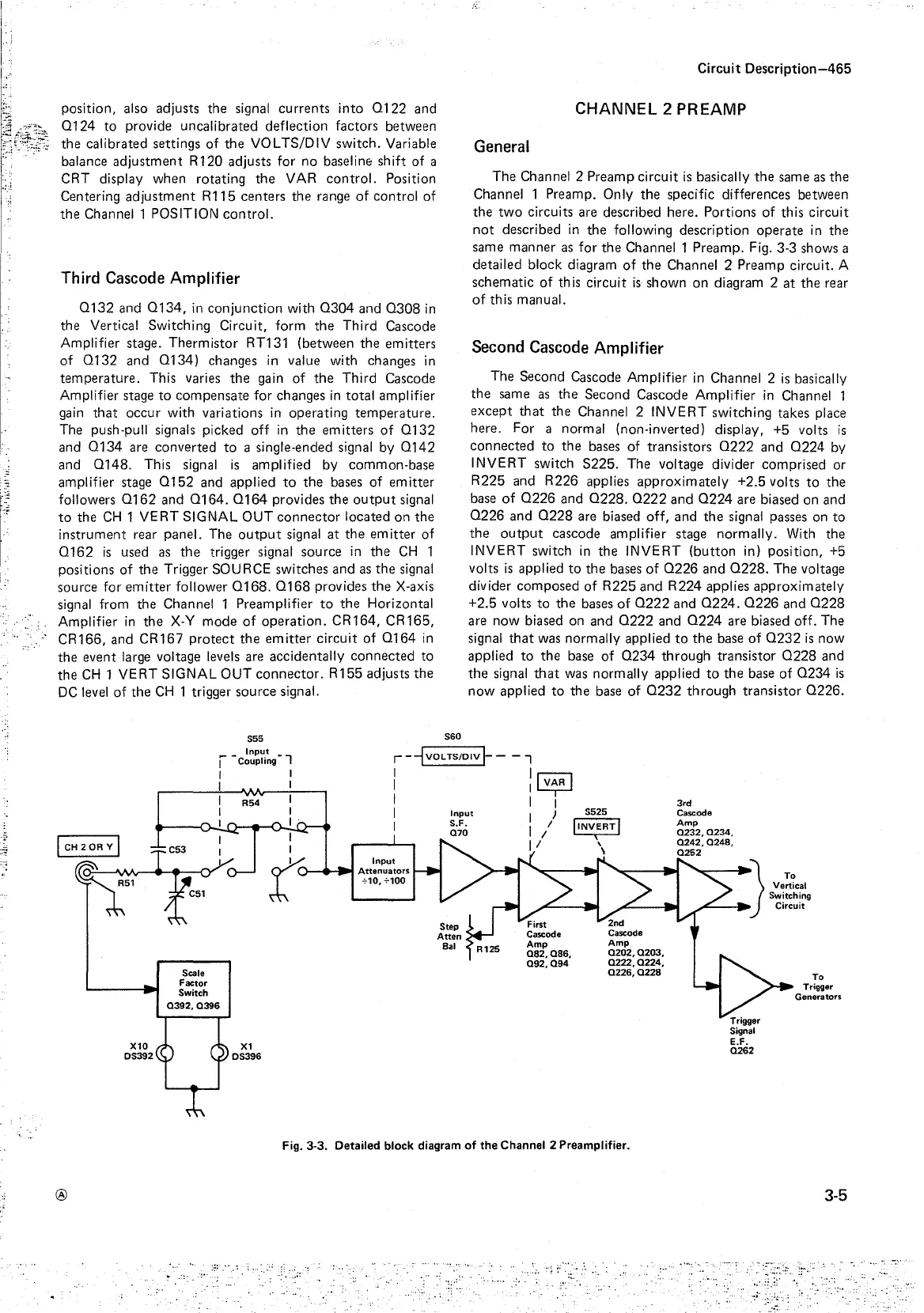
Channel 1 Preamp. Fig. 3-3 shows a
detailed block diagram
of
the
Channel 2 Preamp circuit. A
schematic
of
this
circuit
is
shown
on
diagram 2
at
the
rear
of
this manual.
Second
Cascode
Amplifier
The Second Cascode Amplifier
in
Channel 2
is
basically
the
same
as
the
Second
Cascode Amplifier
in
Channel 1
except
that
the
Channel 2
INVERT
switching takes place
here. For a normal (non-inverted) display, +5 volts
is
connected
to
the
bases of transistors
0222
and
0224
by
INVERT switch
S225.
The voltage divider comprised or
R225
and
R226
applies
approximately
+2.5 volts
to
the
base
of
0226
and
0228.
0222
and
0224
are biased on and
0226
and
0228
are biased
off,
and
the
signal passes on
to
the
output
cascode amplifier stage normally. With the
INVERT switch
in
the
INVERT
(button
in) position, +5
volts
is
applied
to
the
bases
of
0226
and
0228.
The voltage
divider
composed
of
R225
and
R224
applies
approximately
+2.5 volts
to
the
bases
of
0222
and
0224.
0226
and
0228
are
now
biased on
and
0222
and
0224
are biased off. The
signal
that
was normally applied
to
the
base
of
0232
is
now
applied
to
the
base
of
0234
through
transistor
0228
and
the
signal
that
was normally applied
to
the
base
of
0234
is
now
applied
to
the
base
of
0232
through
transistor
0226.
S55
Input
I -Coupling - 1
r-~VOLTS/OIV~-
- 7
®
I I
I I
I I
I
: : I
V~R
I
I I I
I
Input
I )
I
~jo
I/
----
II
t
Input
)-+-a.I
Attenuators
+10,+100
Scale
Factor
Switch
Q392, Q396
S525
I
INV,ERT
I
\
\
Fig. 3-3. Detailed block diagram
of
the
Channel 2 Preamplifier.
Trigger
Signal
E.F.
Q262
To
Trigger
Generators
3-5