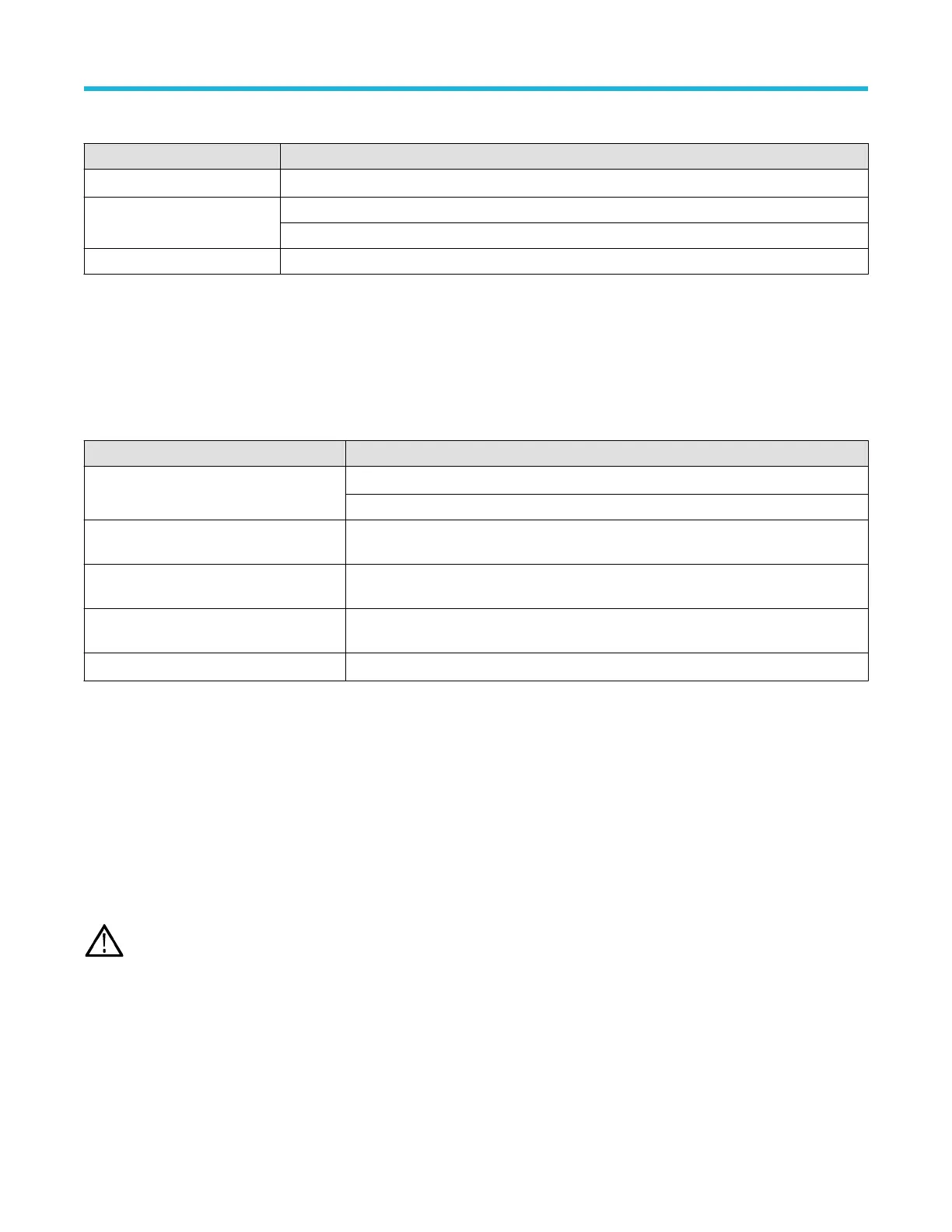
Power requirements
Characteristic Description
Power source voltage 100 V - 240 V
AC RMS
, ±10%, single phase
Power source frequency 50/60 Hz, 100-240 V
400 Hz, 115 V
Power consumption 400 W maximum
Input signal requirements
Keep the input signals within allowed limits to ensure the most accurate measurements and prevent damage to the analog and digital
probes or instrument.
Make sure that input signals connected to the MSO instrument are within the following requirements.
Input Description
Analog input channels, 1 MΩ setting,
maximum input voltage at BNC
300 V
RMS
Measurement Category II
Analog input channels, 50 Ω setting,
maximum input voltage at BNC
5 V
RMS
Digital input channels, maximum input
voltage range at digital inputs
Observe probe ratings: TLP058; ±42 V
P
Ref In maximum input voltage at BNC (rear
panel)
7 V
PP
Aux In trigger input ±5 V
RMS
Installing the instrument in a rack
Use these instructions to install the Low Profile instrument into a standard 19" wide by 24" to 32" deep equipment rack.
The instrument comes equipped with the rack bracket hardware installed on the chassis. Use the bolts and washers from the bag that
ships with the instrument to install the rear rack brackets in the rack.
To use an Low Profile instrument on a bench, purchase and install the MSO58LP/LPD64 Benchtop Conversion kit (Tektronix part number
020-3180-xx). The kit includes chassis feet and a handle, and lets you stack instruments on a bench.
Follow these steps to install the instrument in a rack:
WARNING:
To prevent injury, two people are required to install the instrument.
1. Use two bolts and washers from the supplied hardware to attach one of the rear rack brackets to the rear of the rack. Tighten by hand.
Preface
MSO58LP 5 Series MSO Low Profile Quick Start Manual 17

 Loading...


