Performance Check— Type 503
36. Check Sweep Magnifier Registration
a. Requirement— <0.5 cm shift from magnified sweep to
normal sweep.
b. Set the SWEEP TIME/CM to 1 mSEC.
c. Set the time-mark generator to supply 5-millisecond
markers.
d. Check that the SOURCE switch is set to INT., and adjust
the LEVEL control.
e. Center the first time mark to the graticule vertical
center line with the HORIZONTAL POSITION control.
f. Change the HORIZONTAL DISPLAY switch to X 50,
and recenter the first time mark to the graticule center line.
g. Change the HORIZONTAL DISPLAY switch to SWEEP
NORMAL (X I).
h. Check—No more than 0.5 cm shift of the first time
mark as the HORIZONTAL DISPLAY switch is changed from
X50 to XT.
37. Check Horizontal Drift
a. Requirement— < 4 mm drift from the magnified display
to the normal display.
b. Set the HORIZONTAL DISPLAY SWEEP MAGNIFIED
switch to X50, and check that the first time-mark is at the
graticule center.
c. Change the HORIZONTAL DISPLAY SWEEP MAGNI
FIED switch to X I.
d. Check—After 30 seconds, the marker drift should not
be more than 4 mm.
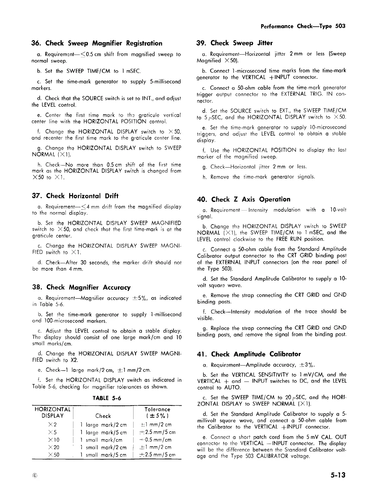
38. Check Magnifier Accuracy
a. Requirement—Magnifier accuracy ± 5 % , as indicated
in Table 5-6.
b. Set the time-mark generator to supply 1-millisecond
and 100-microsecond markers.
c. Adjust the LEVEL control to obtain a stable display.
The display should consist of one large mark/cm and 10
small marks/cm.
d. Change the HORIZONTAL DISPLAY SWEEP MAGNI
FIED switch to X2.
e. Check— 1 large mark/2cm, ± 1 mm/2cm.
f. Set the HORIZONTAL DISPLAY switch as indicated in
Table 5-6, checking for magnifier tolerances as shown.
TABLE 5-6
HORIZONTAL
DISPLAY
Check
Tolerance
(±5%)
X2
1 large mark/2 cm
h i mm/2cm
X 5 1 large mark/5 cm
rh2.5 mm/5 cm
X10 1 small mark/cm
-t-0.5 mm/cm
X20
1 small mark/2 cm
.h i mm/2 cm
X50 1 small mark/5 cm
ih2.5 mm/5 cm
39. Check Sweep Jitter
a. Requirement— Horizontal jitter 2 mm or less (Sweep
Magnified X50).
b. Connect 1-microsecond time marks from the time-mark
generator to the VERTICAL + INPUT connector.
c. Connect a 50-ohm cable from the time-mark generator
trigger output connector to the EXTERNAL TRIG. IN con
nector.
d. Set the SOURCE switch to EXT., the SWEEP TIME/CM
to 5 /<SEC, and the HORIZONTAL DISPLAY switch to X50.
e. Set the time-mark generator to supply 10-microsecond
triggers, and adjust the LEVEL control to obtain a stable
display.
f. Use the HORIZONTAL POSITION to display the last
marker of the magnified sweep.
g. Check—Horizontal jitter 2 mm or less.
h. Remove the time-mark generator signals.
40. Check Z Axis Operation
a. Requirement — Intensity modulation with a 10-volt
signal.
b. Change the HORIZONTAL DISPLAY switch to SWEEP
NORMAL (X I), the SWEEP TIME/CM to 1 mSEC, and the
LEVEL control clockwise to the FREE RUN position.
c. Connect a 50-ohm cable from the Standard Amplitude
Calibrator output connector to the CRT GRID binding post
of the EXTERNAL INPUT connectors (on the rear panel of
the Type 503).
d. Set the Standard Amplitude Calibrator to supply a 10-
volt square wave.
e. Remove the strap connecting the CRT GRID and GND
binding posts.
f. Check— Intensity modulation of the trace should be
visible.
g. Replace the strap connecting the CRT GRID and GND
binding posts, and remove the signal from the binding post.
41. Check Amplitude Calibrator
a. Requirement— Amplitude accuracy, ±3 % .
b. Set the VERTICAL SENSITIVITY to 1 mV/CM, and the
VERTICAL + and — INPUT switches to DC, and the LEVEL
control to AUTO.
c. Set the SWEEP TIME/CM to 2 0-.SEC, and the HORI
ZONTAL DISPLAY to SWEEP NORMAL (X I).
d. Set the Standard Amplitude Calibrator to supply a 5-
millivolt square wave, and connect a 50-ohm cable from
the Calibrator to the VERTICAL -(-INPUT connector.
e. Connect a short patch cord from the 5 mV CAL. OUT
connector to the VERTICAL —INPUT connector. The display
will be the difference between the Standard Calibrator volt
age and the Type 503 CALIBRATOR voltage.
©
5-13