h. Check— A stable display in both positions of the SLOPE
switch.
i. Remove the 10X probe.
Performance Check— Type 503
30. Check Sweep Timing— 1 mSEC/CM
a. Requirement— Sweep accuracy + 3 % (2.4 mm in 8 cm).
b. Set the controls as follows:
SLOPE
COUPLING
SOURCE
LEVEL
HORIZONTAL DISPLAY
VERTICAL
SENSITIVITY
VARIABLE
POSITION
+INPUT
-IN PU T
HORIZONTAL
+INPUT
-IN PUT
SWEEP TIME/CM
+
AC
INT.
Triggered (not AUTO.)
SWEEP NORMAL (X I)
Set to produce a
3-cm display
Set to produce a
3-cm display
Midrange
AC
GND
GND
GND
1 mSEC
c. Set the time-mark generator (item 5 of Recommended
Equipment) to supply 1-millisecond markers.
d. Connect a 50-ohm cable from the time-mark gener
ator output connector to the VERTICAL -{-INPUT connector.
e. Set the VERTICAL SENSITIVITY and the VARIABLE
control so that the display amplitude is approximately 3 cm.
f. Check— 1 marker/cm, ± 3 % (2.4 mm in 8 cm).
31. Check Sweep Length
a. Requirement— Sweep length 10.2 to 10.8 cm.
b. Change the SWEEP TIME/CM to 1 mSEC, the time-
mark generator output to 1-millisecond markers, and the
SOURCE switch to INT.
c. Check— A sweep length of 10.2 cm to 10.8 cm.
32. Check Sweep Timing— 10 /lSEC/CM
a. Requirement—Sweep accuracy + 3 % (2.4 mm in 8 cm).
b. Change the generator output to 10 - microsecond
markers.
c. Change the SWEEP TIME/CM switch to 10/tSEC.
d. Check— One marker/cm, ± 3% .
33. Check Sweep Timing— 1 /xSEC/CM
a. Requirement— Sweep accuracy ±3 % (2.4 mm in 8 cm)
b. Change the time-mark generator output to 1-micro
second markers.
c. Change the SWEEP TIME/CM switch to 1 /tSEC.
d. Connect a 50-ohm cable from the time-mark generator
trigger output connector to the EXTERNAL TRIG. IN con
nector, and set the generator to supply 10-microsecond
triggers.
e. Change the SOURCE switch to EXT.
f. Check—One marker/cm, ± 3% .
34. Check Variable Control Ratio
a. Requirement— >2.5:1 reduction in sweep rates.
b. Rotate the SWEEP TIME/CM VARIABLE control fully
counterclockwise.
c. Check— >2.5 times as many markers in a given display
area.
d. Return the VARIABLE control fully clockwise.
35. Check Sweep Timing
a. Requirement—Sweep accuracy ± 3 % (2.4 mm in 8 cm)
in all SWEEP TIME/CM ranges.
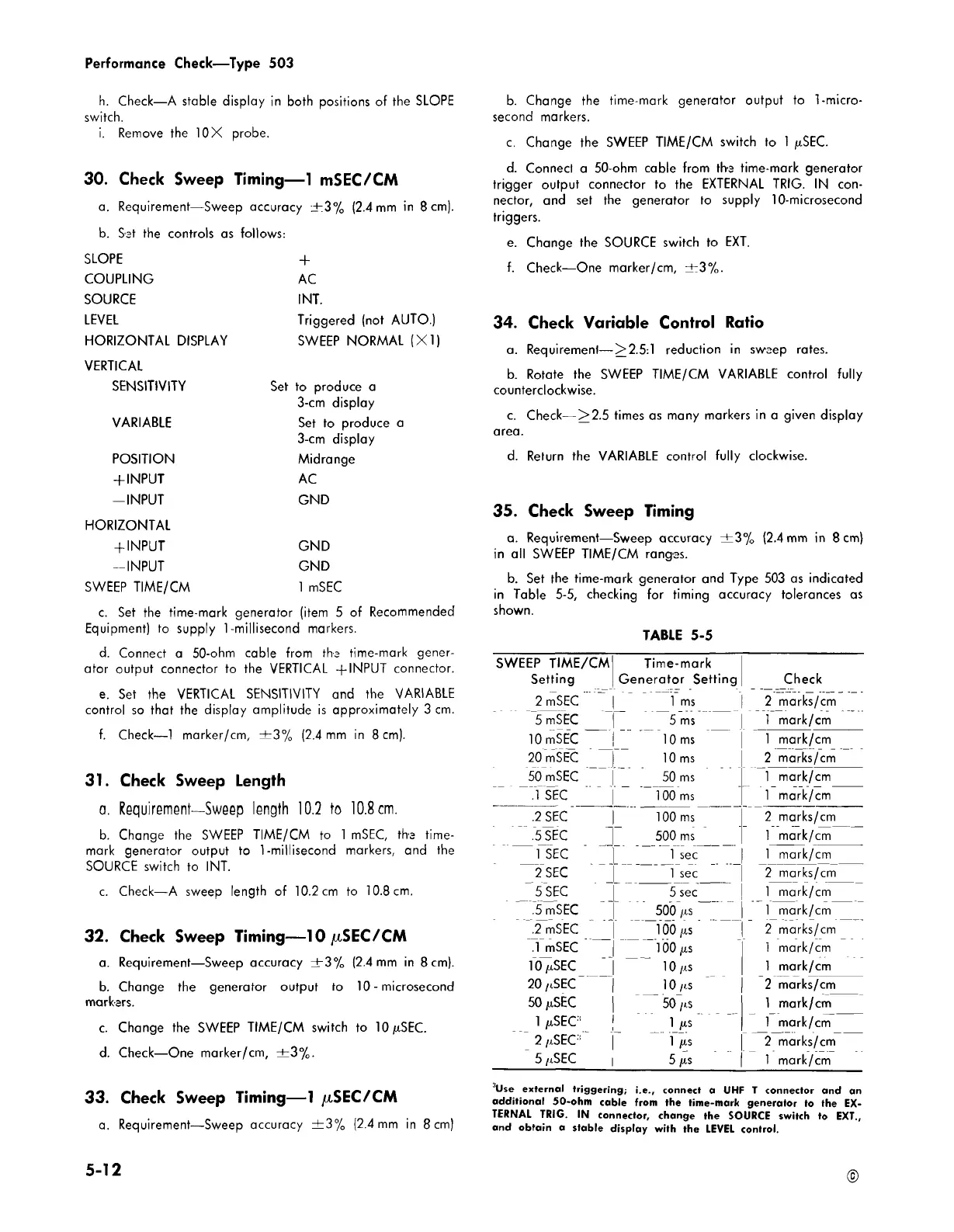
b. Set the time-mark generator and Type 503 as indicated
in Table 5-5, checking for timing accuracy tolerances as
shown.
TABLE 5-5
SWEEP TIME/CM
Time-mark
Setting
Generator Setting Check
2 nTSEC
1 ms
2 marks/cm
5 mSEC
5 ms
1 mark/cm
10 mSEC 10 ms
1 mark/cm
20 mSEC 10 ms 2 marks/cm
50 mSEC
50 ms
1 mark/cm
.1 SEC
100 ms
1 mark/cm
.2 SEC
100 ms
2 marks/cm
.5 SEC 500 ms
1 mark/cm
1 SEC 1 sec
1 mark/cm
2 SEC 1 sec
2 marks/cm
5 SEC
5 sec
1 mark/cm
.5 mSEC
500 jis
1 mark/cm
.2 mSEC
100 jxs
2 marks/cm
.1 mSEC
100 jxs
1 mark/cm
10/cSEC
10 /xs
1 mark/cm
20 /iSEC
10 /is
2 marks/cm
50 jnSEC
50 /is
1 mark/cm
1 ftSEC1
1 ix s 1 mark/cm
2 /cSEC •
1 /ts 2 marks/cm
5 /iSEC
5 1is
1 mark/cm
JUse external triggering; i.e., connect a UHF T connector and an
additional 50-ohm cable from the time-mark generator to the EX
TERNAL TRIG. IN connector, change the SOURCE switch to EXT.,
and obtain a stable display with the LEVEL control.
5-12
©