Calibration— Type 503
Fig. 6-3 Equipment »»tup for powor tup ply ad|u*t and rhocli.
SLOPE
COUPLING
SOURCE
LEVEL
SWEEP TIME/CM
VARIABLE
INTENSITY
HORIZONTAL DISPLAY
VERTICAL
SENSITIVITY
VARIABLE
POSITION
+ INPUT
-IN PUT
HORIZONTAL
SENSITIVITY
VARIABLE
POSITION
+ INPUT
-INPU T
+
AC
INT.
Counterclockwise (but
not AUTO)
1 mSEC
CALIBRATED
(fully clockwise)
Fully counterclockwise
SWEEP NORMAL (XI)
.1 VOLTS/CM
CALIBRATED
(fully clockwise)
Midrange
DC
GND
.1 VOLTS/CM
CALIBRATED
(fully clockwise)
Midrange
GND
GND
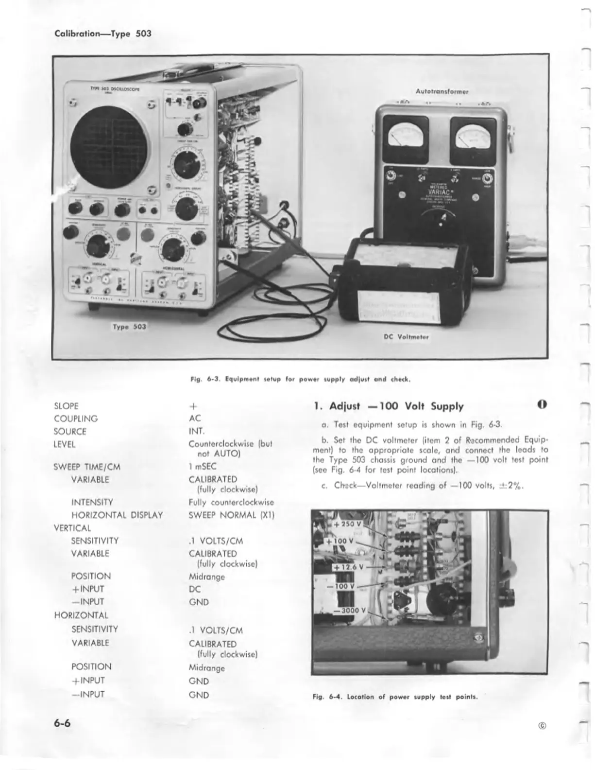
1. Adjust — 100 Volt Supply ©
a. Test equipment setup is shown in Fig. 5-3.
b. Set the DC voltmeter (item 2 of Recommended Equip
ment) to the appropriate scale, and connect the leads to
the Type 503 chassis ground and tho — 100 volt test point
(see Fig. 6 4 for test point locations).
c. Check—Voltmeter reading of —100 volts, ±:2%.
3000 v
Fig 6-4. Location of powor supply test points.
©
6-6