Calibration— Type 503
NOTE
Do not adjust the — 100 ADJ. control unless one
or more of the supply voltages are out o f toler
ance, or unless a complete recalibration of the
instrument is planned.
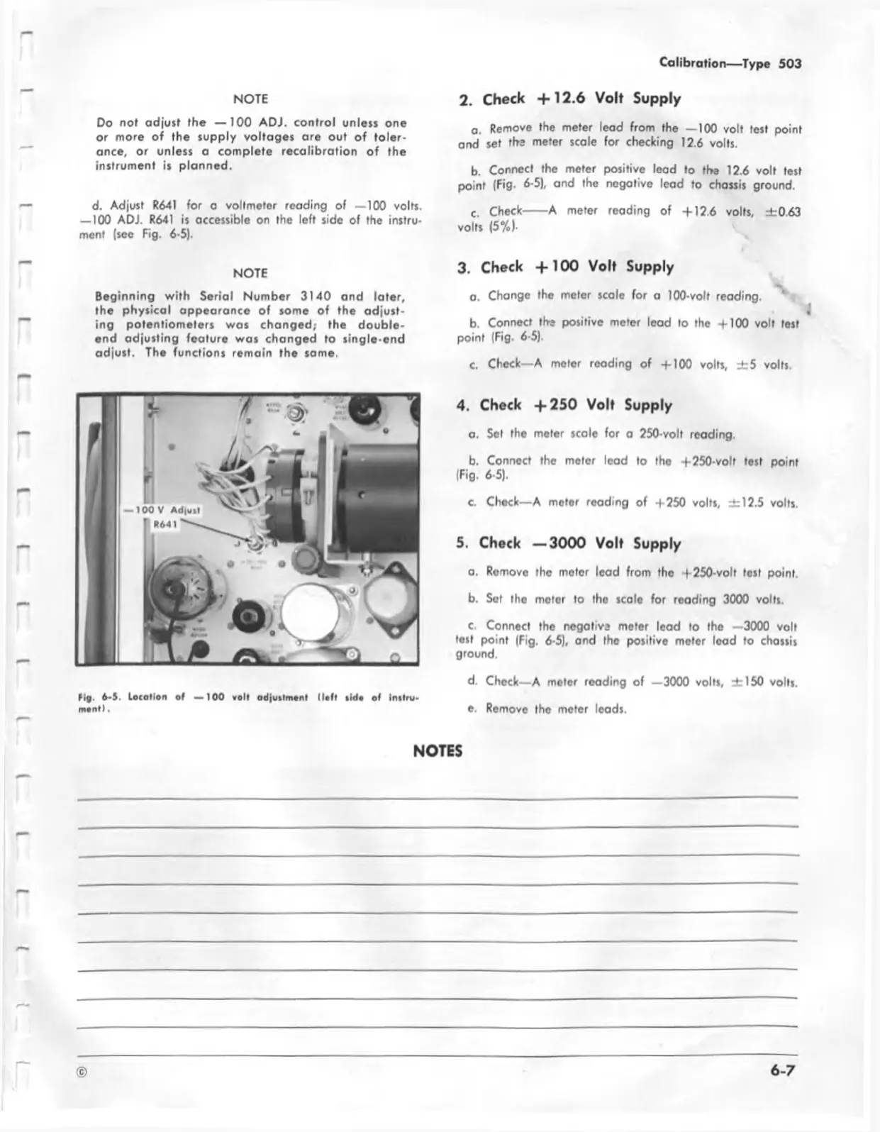
d. Adjust R641 for a voltmeter reading of —100 volts.
— 100 ADJ. R641 is accessible on the left side of the instru
ment (see Fig. 6-5).
NOTE
Beginning w ith Serial Number 3140 and later,
the physical appearance o f some of the adjust
ing potentiometers was changed; the double
end adjusting feature was changed to single-end
adjust. The functions remain the same.
tig . 6-5, loc a tio n o f — 100 vo lt ad |u tlm onl (lo ft tid a of In tlru-
m ont).
2. Check + 1 2 .6 Volt Supply
a. Remove the meter lead from the — 100 volt test point
and set the meter scale for checking 12.6 volts.
b. Connect the meter positive lead to the 12.6 volt test
point (Fig. 6-5), and the negative lead to chassis ground.
c. Check
------
A meter reading of +12.6 volts, ±0.63
volts (5%).
3. Check + 1 0 0 Volt Supply
a. Change the meter scale for a 100-volt reading.
b. Connect tbs positive meter lead to the +100 volt test
point (Fig. 6-5).
c. Check—A meter reading of +100 volts, ± 5 volts.
4. Check + 2 5 0 Volt Supply
a. Set the meter scale for a 250-volt reading.
b. Connect the meter lead to the + 250-volt test point
(Fig. 6-5).
c. Check— A meter reading of +250 volts, ±12.5 volts.
5. Check — 3000 Volt Supply
a. Romove the meter lead from tho +250-volt lost point
b. Set the meter to tho scale for reading 3000 volts.
c. Conned the negotivs meter lead to the —3000 volt
test point (Fig. 6-5), ond the positive meter lead to chassis
ground.
d. Chock—A motor reading of —3000 volts, ±1 50 volts.
e. Remove the meter leads.
NOTES
©
6-7