C alibration— Type 503
e. Connect a 50-ohm cable from the UHF T connector
to the EXTERNAL TRIG. IN connector.
f. Rotate the LEVEL control to a point near 0 to obtain
a stable display, similar to Fig. 6-22.
g. Adjust the generator output for a 3-cm spacing hori
zontally, and center the display with the HORIZONTAL
POSITION control.
NOTE
To attain the desired deflection it w ill be neces
sary to add or remove the 50-ohm termination
a n d /o r the X10 attenuator. This w ill not affect
the accuracy of the time-constant adjustments.
h. Check—For an optimum square wave with flat lop,
similar to Fig. 6-22 (B).
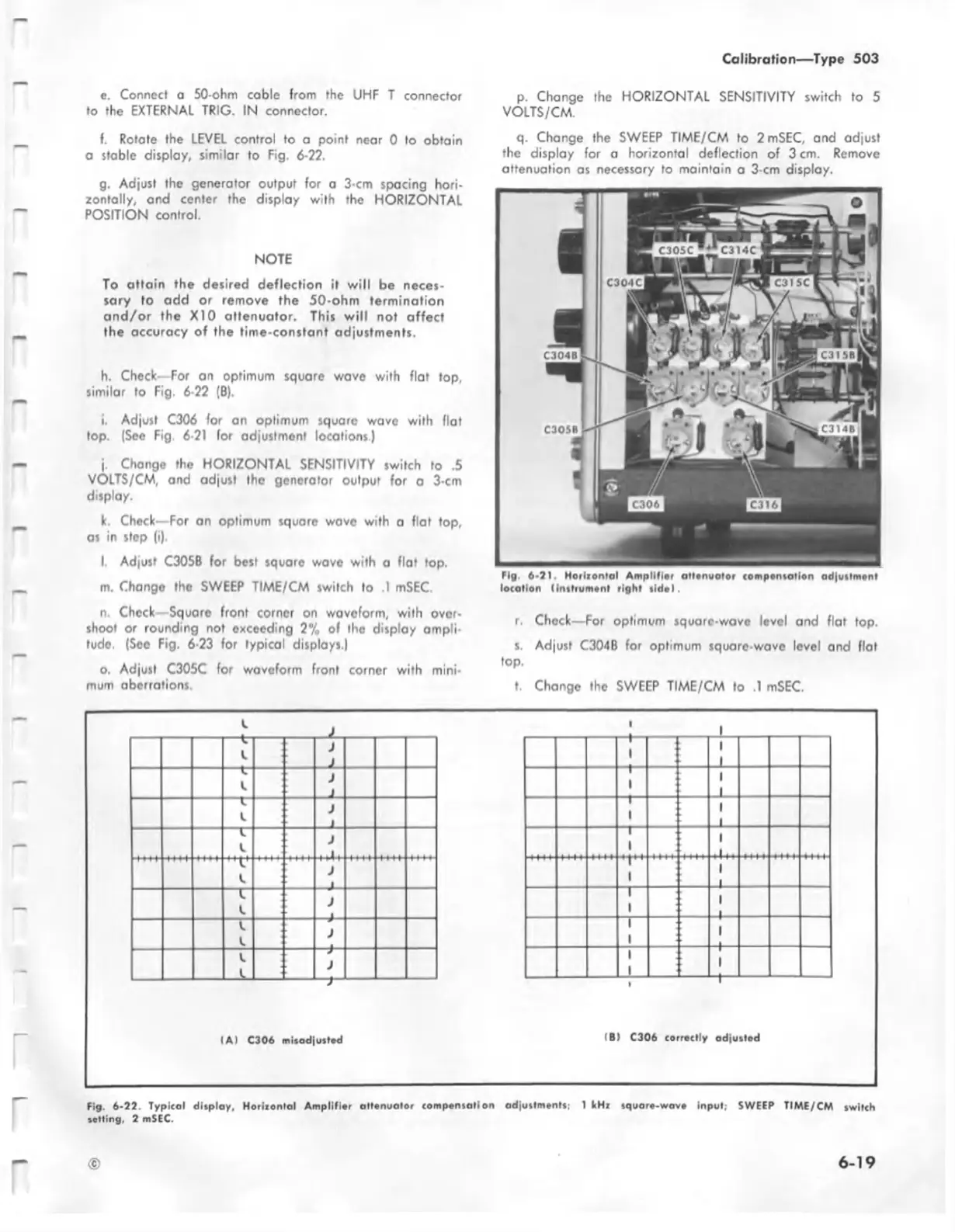
i. Adjust C306 for an optimum square wave with flat
top. (See Fig. 5-21 for adjustment locations.)
j. Change the HORIZONTAL SENSITIVITY switch to .5
VOLTS/CM, and adjust the generator output for a 3-cm
display.
k. Check—For an optimum square wave with a flat top,
as in step (i).
l. Adjust C305B for best square wave with a flat top.
m. Change the SWEEP TIME/CM switch to .1 mSEC.
n. Check Square front corner on waveform, with over
shoot or rounding not exceeding 2% of the display ampli
tude. (See Fig. 6-23 for typical displays.)
o. Adjust C305C for waveform front cornor with mini
mum aberrations.
p. Change the HORIZONTAL SENSITIVITY switch to 5
VOLTS/CM.
q. Change the SWEEP TIME/CM to 2 mSEC, and adjust
the display for a horizontal deflection of 3 cm. Remove
attenuation as necessary to maintain a 3-cm display.
Fig. 6-21. H oriionfal Am plifier attenuotor compensation adjustment
location (instrument right tid e).
r. Check—For optimum square-wave level and flat top.
s. Adjust C304B for optimum square wave level and flat
top.
t. Change the SWEEP TIME/CM to .1 mSEC.
1
—I—
1
1
1
t
1
1
1
1
1
1
1
1
1
i l l .
’ 1 "
1
1
I
1
1
1
_ l
__
1
1
1
1
1
—♦—
I A) C306 misadjusted
IB) C306 correctly adjusted
Fig. 6-22. Typicol display, H oriiontal Am plifier attenuator compensation adjustments; 1 kHx square-wave input, SWEEP TIME/CM switch
setting, 2 mSEC.
©
6 -1 9