Calibration— Type 503
-
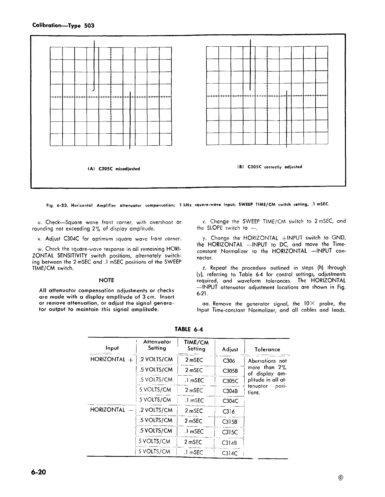
(A ) C305C misadjiJ S te d
(B) C305C correctly o
djusted
Fig. 6-23. Horizontal Amplifier attenuator compensation; 1 kHz square-wave input; SWEEP TIME/CM switch setting, .1 mSEC.
u. Check—Square wave front corner, with overshoot or
rounding not exceeding 2% of display amplitude.
v. Adjust C304C for optimum square wave front corner.
w. Check the square-wave response in all remaining HORI
ZONTAL SENSITIVITY switch positions, alternately switch
ing between the 2 mSEC and .1 mSEC positions of the SWEEP
TIME/CM switch,
NOTE
A ll attenuator compensation adjustments or checks
are made with a display amplitude of 3 cm. Insert
or remove attenuation, or adjust the signal genera
tor output to maintain this signal amplitude.
x. Change the SWEEP TIME/CM switch to 2 mSEC, and
the SLOPE switch to —.
y. Change the HORIZONTAL +INPUT switch to GND,
the HORIZONTAL —INPUT to DC, and move the Time-
constant Normalizer to the HORIZONTAL —INPUT con
nector.
z. Repeat the procedure outlined in steps (h) through
(y), referring to Table 6-4 for control settings, adjustments
required, and waveform tolerances. The HORIZONTAL
—INPUT attenuator adjustment locations are shown in Fig.
6-21.
aa. Remove the generator signal, the 10X probe, the
Input Time-constant Normalizer, and all cables and leads.
TABLE 6-4
! Attenuator TIME/CM
Input Setting 1 Setting
Adjust
HORIZONTAL + .2 VOLTS/CM 2 mSEC
C306
| .5 VOLTS/CM | 2 mSEC
C305B
| .5 VOLTS/CM .1 mSEC~ "
C305C
5 VOLTS/CM j 2 mSEC "
C304B
5 VOLTS/CM | .1 mSEC ~
C304C
HORIZONTAL - .2 VOLTS/CM 2 mSEC
C316
.5 VOLTS/CM 2 mSEC
C315B
.5 VOLTS/CM | .] mSEC
C315C |
5 VOLTS/CM | ~TmSEC
C314B
| 5 VOLTS/CM |
.1
mSEC _ j
C314C |
Tolerance
Aberrations not
more than 2%
of display am
plitude in all at
tenuator posi
tions.
6-20
©