Current Ranges 10/100 mV/A
Maximum Working Voltage
1
Table 3: Voltage and current ratings on
page 9
30 Vms,42 Vpk, 60 VDC, for voltages above
these limits, use insulated conductors only.
Maximum Float Voltage Table 3: Voltage and current ratings on
page 9
Frequency Range DC to 100 kHz (-3 dB)
Battery Type and Life, typical 9V NEDA 1604A, IEC 6LR61 40 hours minimum
(1 each)
DC signal linearity, typical Figure 8: DC signal linearity in the 10 mV/A
range, typical on page 11
Phase shift, typical Figure 9: Phase versus frequency at 1 A peak,
typical on page 12
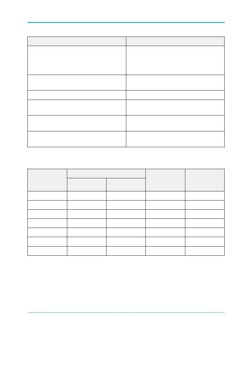
Table 3: Voltage and current ratings
Rating Maximum working current (A) Maximum
working voltage
(V)
Maximum
floating
Range 10 mV/A Range 100 mV/A
DC 100
2
10 600 600
DC + peak AC 100
2
10 600 600
AC peak 100 10 600 600
AC peak-peak 200 20 1200 -
RMS CAT III 70.7 7.07 600 600
RMS CAT II 70.7 7.07 600 600
RMS CAT I 70.7 7.07 600 600
1
An insulated conductor is any conductor that is surrounded by an insulating material that is capable of
isolating the voltage present on the conductor. Lacquer coatings like those typically found on
transformer windings do not provide sufficient, reliable insulation for use with current probes. The
lacquer coating can be easily nicked or damaged, which compromises the insulating capabilities of the
lacquer coating.
2
See frequency derating information in Figure 7: Maximum current versus frequency on page 11.
Maintenance
A622 Instructions 9