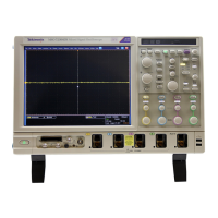
EasyManuals Logo

Tektronix MSO71604C User Manual

Tektronix MSO71604C
222 pages
To Next Page IconTo Next Page
To Previous Page IconTo Previous Page
Page #106 background image
Pinpoint trigge
rs
4. Select the bus.
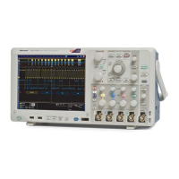
5. Select the bus signal to trigger on.
6. Depending on your Trigger On choice
and your bus type, make the required
selections for the bus.
See the online help for additional help
setting up a bus.
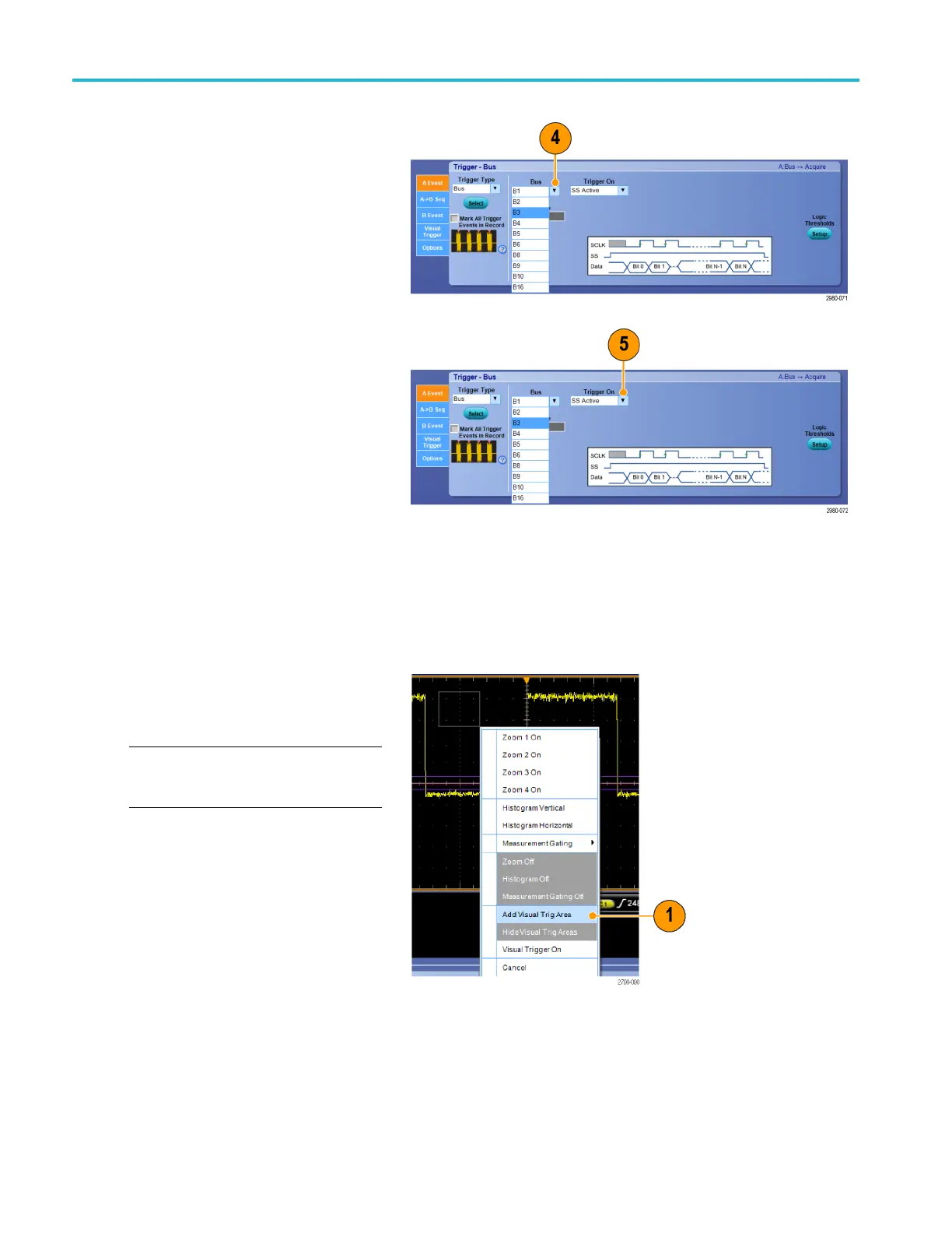
Triggering using Visual Triggers (Visual Triggering)
Visual triggering allows you to create trigger conditions directly on the display screen. (Visual Triggers are available as an
option on some m odels.)
1. Create a visual trigger area by left
clicking and dragging a box on the
display. Then select Add Visual Trig Area
from the menu.
NOTE. This same menu allows you to hide
or show all visual trigger areas and toggle
visual triggering on and off.
84 MSO/DPO70000DX, MSO/DPO70000C, DPO7000C, and MSO/DPO 5000B Series U ser M anual

Table of Contents

Other manuals for Tektronix MSO71604C

Questions and Answers:

Question and Answer IconNeed help?

Do you have a question about the Tektronix MSO71604C and is the answer not in the manual?

Tektronix MSO71604C Specifications

General IconGeneral
Bandwidth16 GHz
Channels4
Sample Rate50 GS/s
Analog Channels4
Digital Channels16
Rise Time22 ps
Input CouplingAC, DC, GND
Operating Temperature0 °C to +50 °C
Vertical Resolution8 bits
Display12.1-inch LCD
Input Impedance1 MΩ
Maximum Input Voltage5 Vrms
Trigger TypesEdge, Pulse, Runt, Window, Logic, Setup/Hold, Rise/Fall Time, Video, Serial
InterfaceUSB, LAN

Related product manuals