Appendix D
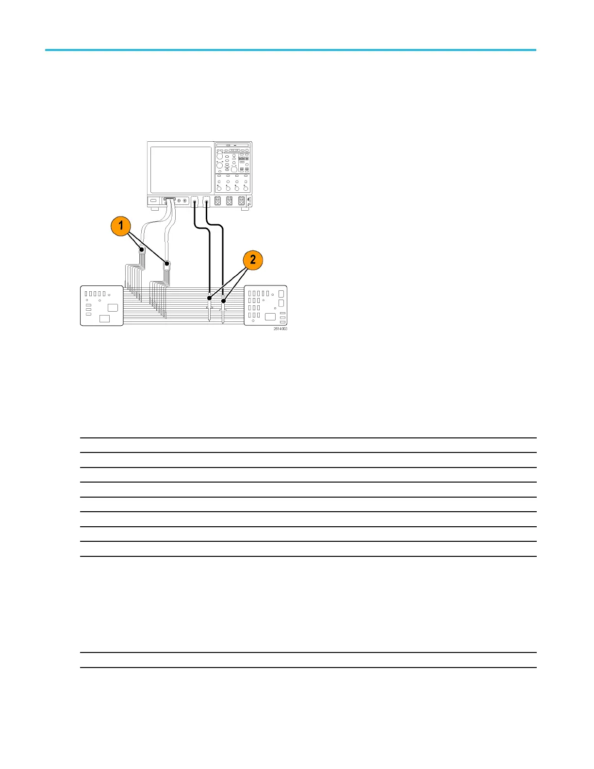
Typical application
1. Use the P6616 probe to view digital signals on a system bus.
2. Use an analog probe, such as the TPP0500/B or TPP1000 passive probe to view analog waveform information.
Accessories
The following standard accessories ship with the probe and are shown in the illustration on the following
page.
Item Description Quantity Part number
— Logic probe accessory kit Item 1–6 020-2662-XX
1 Extension ground tip
1 set of 20
020-2711-XX
2 Probe tip
1 set of 10
131-5638-11
3
IC grabber 1 set of 20
020-2733-XX
4 Probe tip holder 2 ea 352-1115-XX
5
8” Ground lead 1 set of 2
020-2713-XX
6
3” Ground lead 1 set of 8
020-2712-XX
Instructions
1
1 ea 071-2831-XX
1
Instructions are included with the probe, but not in the accessory kit.
The instructions can be downloaded at www.tektronix.com/manuals.
These optional accessories can be ordered for your probe:
Description Part number
P6960 Probe D-MA X Footprint to Square Pin Header Adapter
NEX-P6960PIN
190 MSO/DPO70000DX, MSO/DPO70000C, DPO7000C, and MSO/DPO 5000B Series U ser M anual
 Loading...