Performance Verification
30
P5205 Instruction Manual
NOTE. These procedures assume that you are using an oscilloscope
that automatically displays the correct volts/division scale factor for
the attenuation setting of the probe. If not, you must take the
attenuation setting of the probe into account when setting the
volts/division on the oscilloscope.
Differential Gain Accuracy
1. Usea50Ω coaxial cable to connect the generator trigger output
to channel 2 of the oscilloscope.
2. Set the oscilloscope trigger edge source to channel 2.
3. Set the volts/division on both channels of the oscilloscope to
10 V.
4. Set the sec/div to 200 s, and the acquisition mode to average 32.
5. Connect the Modified BNC adapter to the output connector of the
calibration generator.
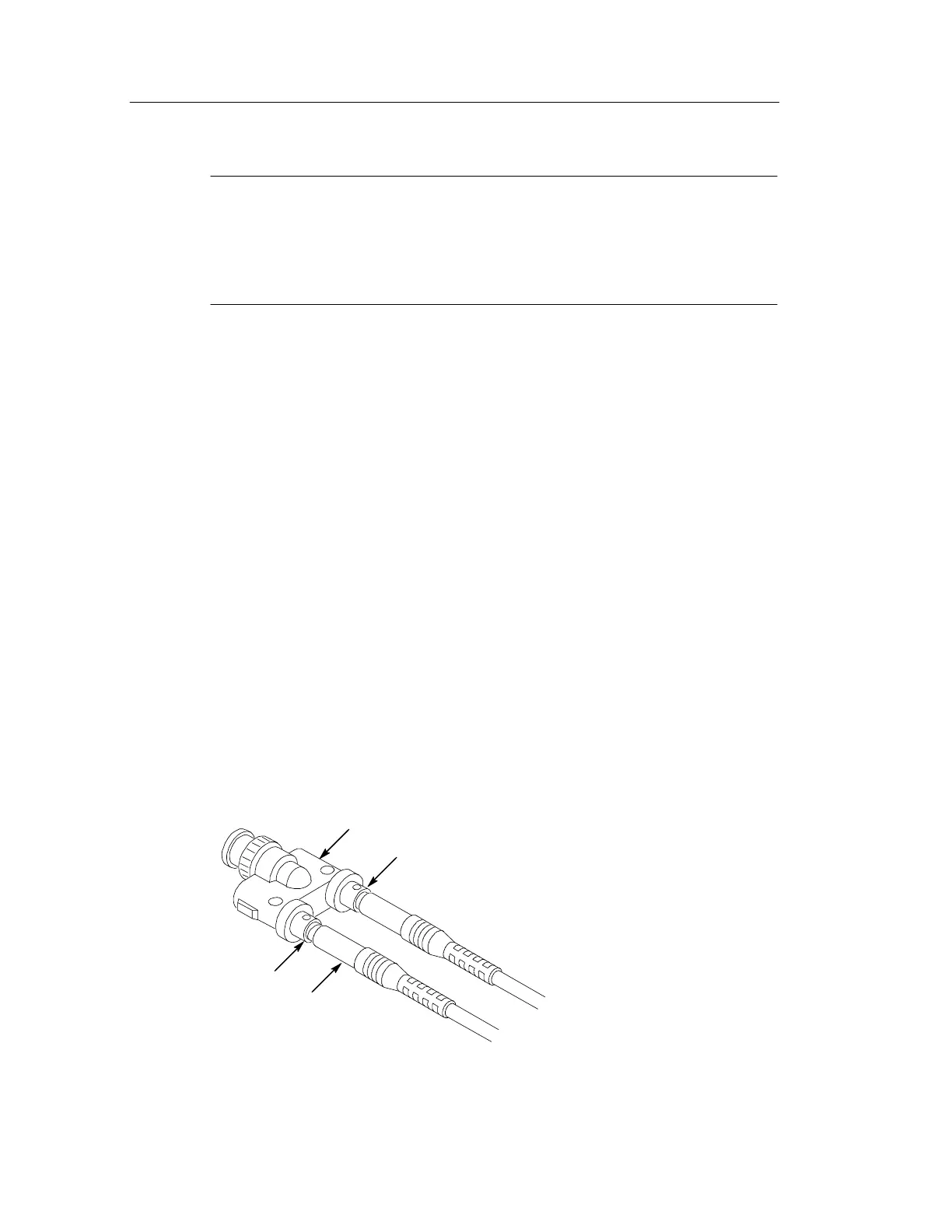
6. Attach the differential probe input leads (without attachment
accessories) by sliding the banana plug of the leads onto the
binding posts metal sleeves on the Modified BNC adapter (see
Figure 13).
(+) Post
(--) Post
Modified BNC adapter
Banana plug of probe
input lead
Figure 13: Slide probe leads onto the binding posts