In Detail
1–10
P6015A Instruction Manual
Maximum Input Voltage
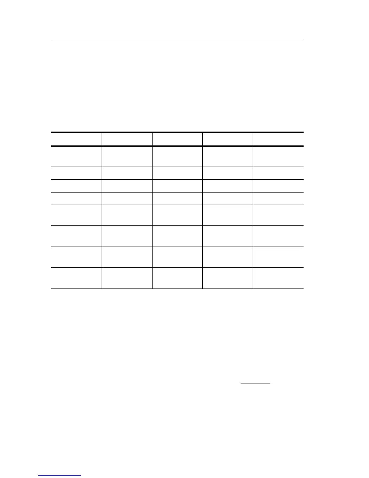
Table 1–1 and the following paragraphs indicate conditions where
the maximum input of the P6015A is reduced.
Table 1–1: Maximum Input Voltage
1,2,3
Max. On Time ≥30 Minutes <30 Minutes ≥15 Minutes <15 Minutes
Temperature
Range °C
0 to 35 0 to 35 36 to 50 36 to 50
V
RMS
4,5,6
14 kV 20 kV 14 kV 20 kV
V
DC
14 kV 20 kV 14 kV 20 kV
V
(DC+PK
AC)
28 kV 40 kV 28 kV 40 kV
V
(Peak
Pulse)
10% Duty Cycle
28 kV 40 kV 28 kV 40 kV
V
(Peak
Pulse)
20% Duty Cycle
25 kV 36 kV 25 kV 36 kV
V
(Peak
Pulse)
30% Duty Cycle
23 kV 33 kV 23 kV 33 kV
V
(Peak
Pulse)
50% Duty Cycle
18 kV 28 kV 18 kV 28 kV
1
Voltage readings are based on a thermal time constant of 30 minutes with
no more than a 60_ internal temperature rise. Internal component heating
is not to exceed 4 W at less than 30 minutes or 2 W at greater than
30 minutes. If the 4 W limit is exceeded in less than 30 minutes, then a
cool-down period of up to 2.5 hours is required for any further probe use.
2
Voltage ratings are based on a thermal time constant of 30 minutes.
3
The maximum pulse duration must not exceed 100 ms (see the derating
chart in Figure 1–5 on page 1–13).
4
RMS=Root Mean Square=rms=The square root of the average of the sum of
the squares of the instantaneous voltage in one cycle = .
ȍ
(fx
i
)
2
ńn
Ǹ
5
RMS=(1/2 Peak V @ 25% DF)=(500 V
pk
2)=250 V
rms
(DF = Duty Factor)
6
RMS=[(V pk)
2
(DF)]
1/2