Adjustments
2–8
P6015A Instruction Manual
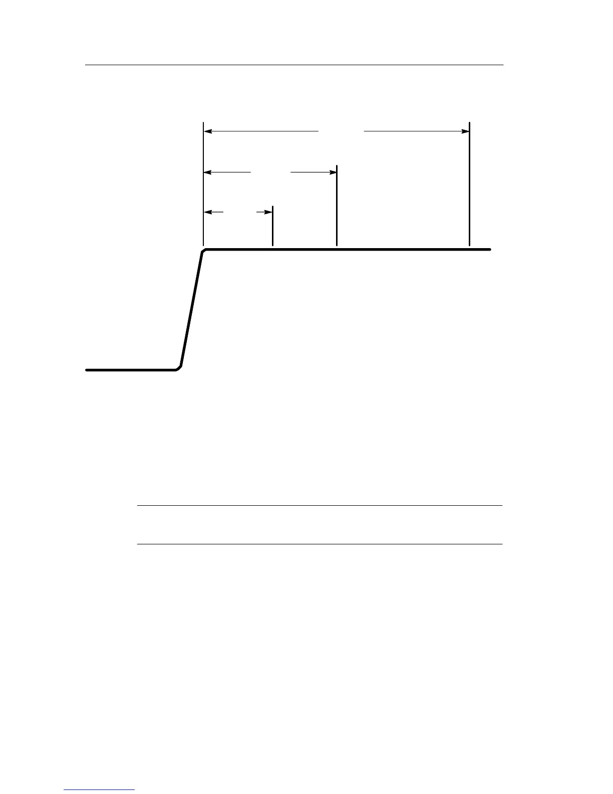
100 ms
R4,C2
200 ms
R2,C1
50 ms
R5,C4
Figure 2–3: Periods Affected by Compensation Adjustments
6. Adjust R2 and C1 to flatten the area 200 ms from the leading
corner. Refer to Figure 2–3 to locate the zones affected by the
adjustments in this and the following steps.
NOTE. Figure 2–3 shows an idealized waveform. The displayed
waveform will include some ground lead ringing.
7. Adjust R4 and C2 to flatten the area 100 ms from the leading
corner.
8. Adjust R5 and C4 to flatten the area 50 ms from the leading
corner.
Adjustments R2, R4, R5, C1, C2, C4, and C5 interact. Steps 4 and 6
through 8 may have to be repeated several times to achieve optimum
flatness.