sc
501
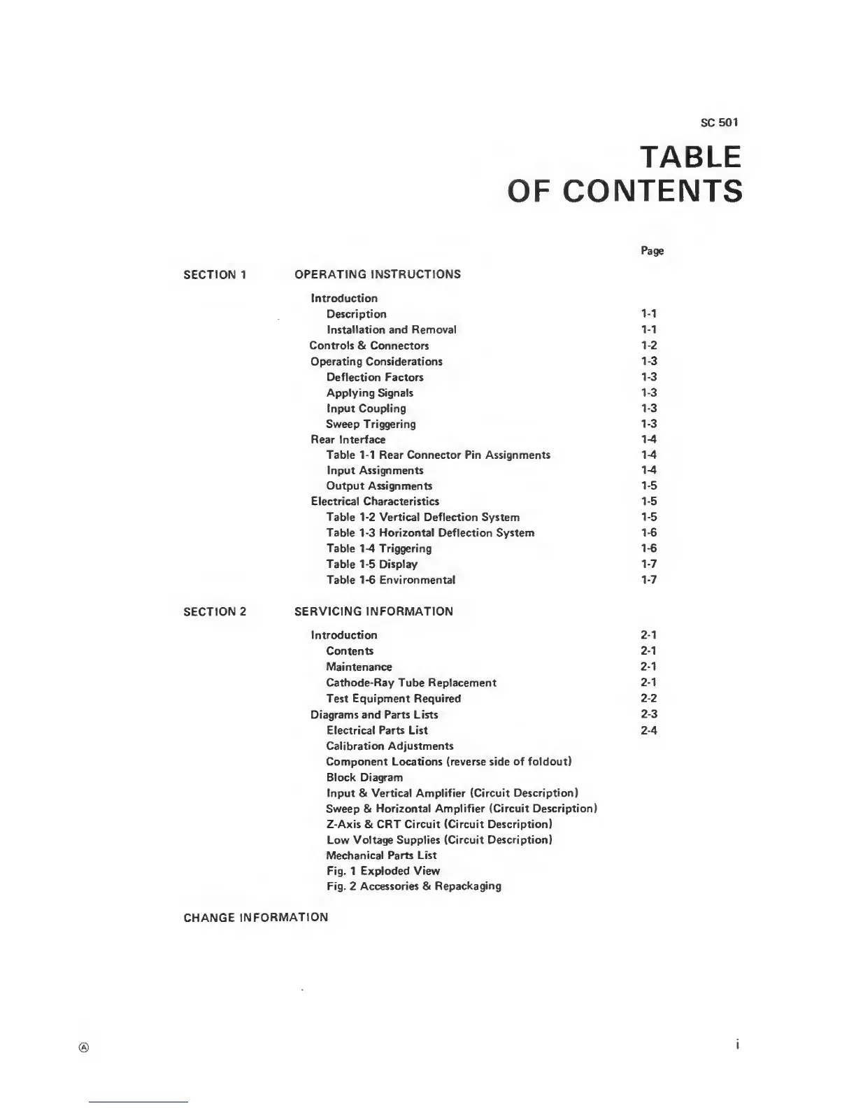
TABLE
OF
CONTENTS
Page
SECTION 1
OPERATING INSTRUCTIONS
Introduction
Description
1-1
Installation and Removal
1-1
Controls
& Connectors
1-2
Operating Considerations
1-3
Deflection Factors
1-3
Applying Signals
1-3
Input
Coupling
1-3
Sweep
Triggering
1-3
Rear Interface
1-4
Table
1-1
Rear Connector Pin Assignments
1-4
Input
Assignments
1-4
Output Assignments
1-5
Electrical Characteristics
1-5
Table
1-2
Vertical Deflection
System
1-5
Table
1-3
Horizontal Deflection System
1-6
Table
1-4
Triggering
1-6
Table
1-5
Display
1-7
Table
1-6
Environmental
1-7
SECTION
2 SERVICING
INFORMATION
Introduction
2-1
Contents
2-1
Maintenance
2-1
Cathode-Ray Tube
Replacement
2-1
Test Equipment Required
2-2
Diagrams and Parts Lists
2-3
Electrical Parts List
2-4
Calibration
Adjustments
Component Locations (reverse side of foldout)
Block Diagram
Input &
Vertical
Amplifier
(Circuit Description)
Sweep
&
Horizontal Amplifier (Circuit Description)
Z-Axis & CRT Circuit (Circuit Description)
Low Voltage Supplies
(Circuit Description)
Mechanical
Parts List
Fig. 1 Exploded
View
Fig. 2 Accessories &
Repackaging
CHANGE
INFORMATION