Operating
Instructions—SC
501
REAR INTERFACE
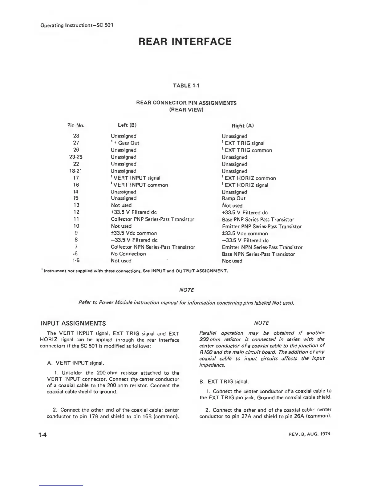
TABLE
1-1
REAR
CONNECTOR
PIN
ASSIGNMENTS
(REAR
VIEW)
Pin No.
Left (B)
Right
(A)
28 Unassigned
Unassigned
27
*
-t-
Gate
Out
‘EXT TRIG signal
26 Unassigned
‘
EXT TRIG common
23-25
Unassigned
Unassigned
22
Unassigned
Unassigned
18-21
Unassigned
Unassigned
17
‘VERT INPUT
signal
‘
EXT HORIZ common
16
‘VERT INPUT common
‘EXT
HORIZ signal
14
Unassigned
Unassigned
15 Unassigned
Ramp Out
13
Not used
Not used
12 +33.5
V
Filtered
dc
+33.5
V Filtered dc
11
Collector PNP Series-Pass
Transistor
Base
PNP
Series-Pass Transistor
10
Not used
Emitter
PNP
Series-Pass Transistor
9 ±33.5
Vdc common
±33.5
Vdc common
8 —33.5
V
Filtered
dc
—33.5
V Filtered
dc
7
Collector NPN
Series-Pass
Transistor
Emitter NPN Series-Pass Transistor
-6
No Connection
Base
NPN Series-Pass Transistor
1-5
Not used
Not used
*
Instrument not supplied
with these connections.
See INPUT
and OUTPUT
ASSIGNMENT.
NOTE
Refer
to
Power
Module instruction
manual for
information concerning pins labeled
Not
used.
INPUT ASSIGNMENTS
The VERT INPUT signal,
EXT TRIG signal
and
EXT
HORIZ signal
can be applied
through
the rear
interface
connectors if
the
SC 501 is modified
as
follows:
A. VERT INPUT signal.
1. Unsolder the 200 ohm resistor
attached
to
the
VERT
INPUT connector.
Connect tl\e center conductor
of a coaxial cable
to
the 200 ohm
resistor. Connect the
coaxial cable shield
to ground.
2. Connect the other end
of the coaxial cable: center
conductor
to
pin
17B
and
shield
to
pin
16B
(common).
NOTE
Parallel operation
may
be
obtained if
another
200 ohm
resistor
is
connected in series
with
the
center conductor of
a
coaxial cable to the
junction
of
R100 and the main circuit board. The
addition
of
any
coaxial cable
to
input circuits affects
the input
impedance.
B. EXT TRIG
signal.
1 .
Connect the center conductor of
a
coaxial
cable
to
the EXT TRIG pin jack. Ground the
coaxial
cable
shield.
2.
Connect the other end of the
coaxial
cable:
center
conductor to pin 27A
and
shield
to
pin 26A
(common).
1-4
REV. B,
AUG.
1974