Push menu button Select menu option Select setting
Measure Source CH1
Measurements Peak-Peak
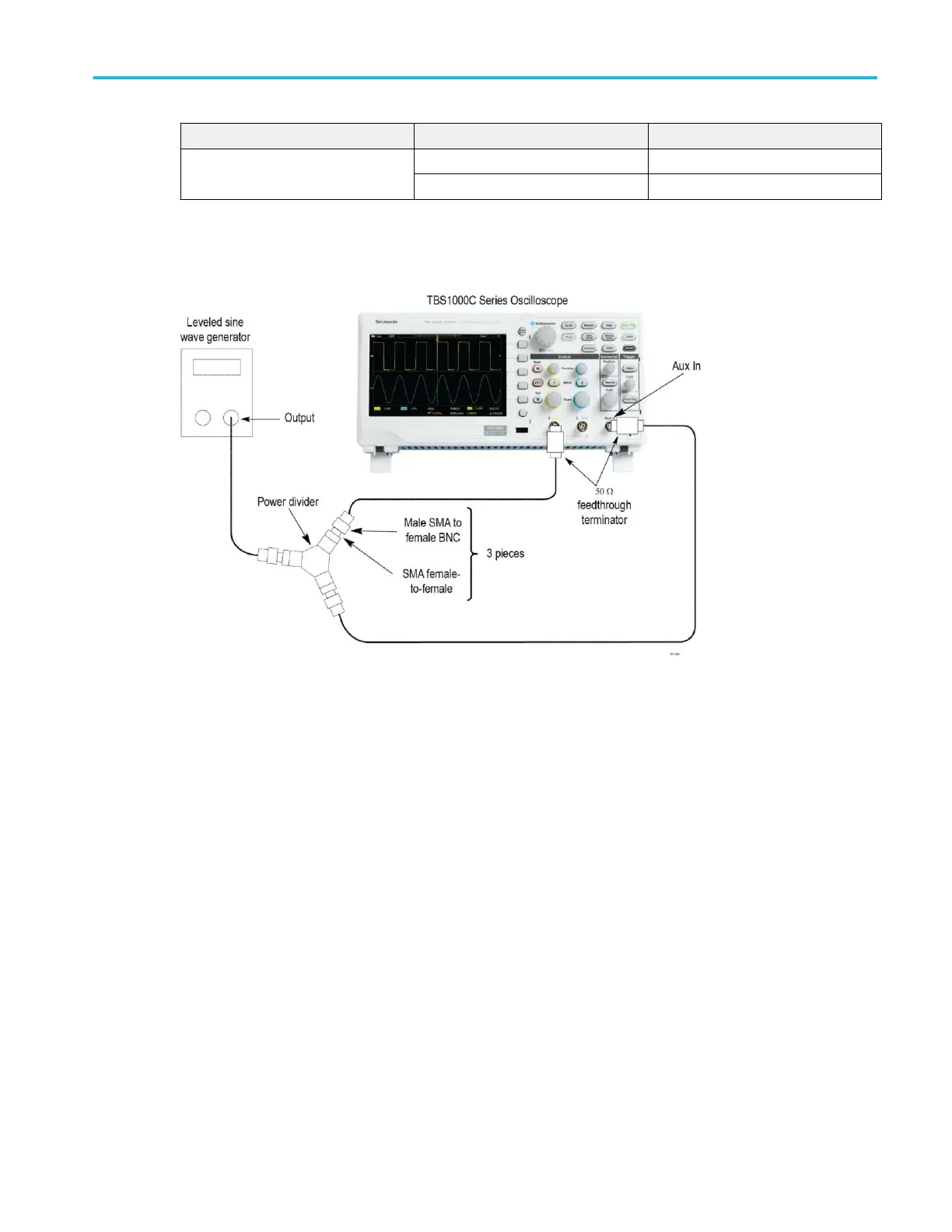
2. Connect the oscilloscope to the leveled sine wave generator as shown in the following figure, using channel 1 and AUX IN.
3. Set the oscilloscope Vertical Scale (volts/division) to 100 mV/div.
4. Set the oscilloscope Horizontal Scale (seconds/division) to 20 ns/div.
5. Set the leveled sine wave generator frequency to 10 MHz.
6. Set the sine wave generator output level to approximately 300 mV
p-p
into the power splitter. This is about 200 mV
p-p
on
channel 1 of the oscilloscope.
The AUX IN input will also be receiving approximately 200 mV
p-p
. Small deviations from the nominal 200 mV
p-p
oscilloscope
display are acceptable.
7. Set the leveled sine wave generator frequency to:
■
200 MHz if you are checking a TBS1202C
■
100 MHz if you are checking a TBS1102C
■
70 MHz if you are checking a TBS1072C
■
50 MHz if you are checking a TBS1052C
8. Set the oscilloscope Horizontal Scale (seconds/division) to 4 ns/div.
9. Push the Trigger Level knob to activate the Set To 50% feature. Rotate the Trigger Level knob to adjust the trigger level as
necessary and then check that triggering is stable.
10. Set the oscilloscope Horizontal Scale (seconds/division) to 2 ns/div.
11. Push the Trigger Level knob to activate the Set To 50% feature. Rotate the Trigger Level knob to adjust the trigger level as
necessary and then check that triggering is stable.
Performance verification
TBS1000C Series Specification and Performance Verification 21

 Loading...