Performance Ve rification
1. Set up the osc il
loscope as shown in the following table:
Push menu button Select menu option Select setting
Default Setup
——
Channels 1, 2, 3
2
, 4
2
Probe 1X
Channels 1, 2, 3
2
, 4
2
Volts/Div 50 mV/div
Source
Ext
1
Trig Menu
Mode Auto
Acquire
Sample
—
Source Channel under test
Measure
Type Mean
1
The test operates without a trigger. To maintain uniformity and to avoid false triggering on noise, the Ext trigger is
the recomm e nd ed source.
2
Available only on a 4-channel oscilloscope.
2. Make a spreadsheet approximately as shown in the example in Appendix A.
You only need to enter the values for column A and the equations. The values
incolumnsB,C,D,E,F,andGareexamplesofthemeasuredorcalculated
values.
The PDF version of the service manual (which you can download from
www.tektronix.com/manuals), includes an empty spreadsheet for your
convenience. To access and save the test spreadsheet, see the instructions
in Appendix A: Example of a Vertical Position Accuracy Test Spreadsheet
on page A-1.
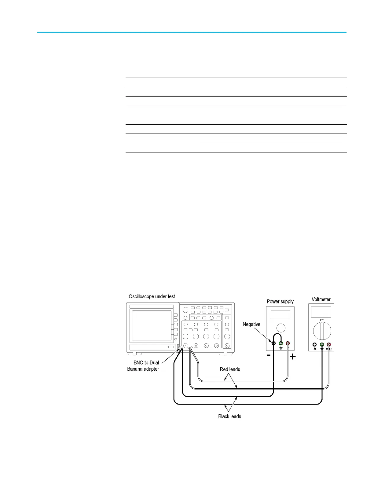
3. Connect the oscilloscope, p ow er supply, and voltmeter as shown in the
following figure:
TBS1000 Series Oscilloscope Service Manual 4–11
 Loading...


