Command Descriptions
2–138
TDS Family Oscilloscope Programmer Manual
HARDCopy:PALEtte
PALEtte
:
<Space>
?
CURRent
HARDCopy
HARDCopy
HARDCOPY:PALETTE HARDCOPY
would print each copy made using the hardcopy palette.
HARDCopy:PORT
Selects where to send the hardcopy data on the next hardcopy command (i.e.
HARDCOPY START command). This is equivalent to setting Port in the
Hardcopy menu.
Hardcopy
HARDCopy, LIMit:HARDCopy
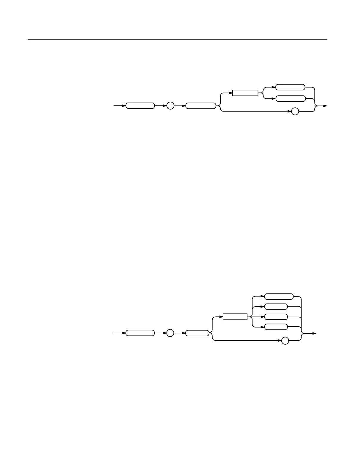
HARDCopy:PORT { CENtronics | FILE (File System only) | GPIb |
RS232 }
HARDCopy:PORT?
PORT
:HARDCopy
RS232
?
CENtronics
FILE
GPIb
<Space>
CENtronics specifies that the hardcopy is sent out the Centronics port (available
with the RS232/Centronics Hardcopy Interface).
FILE specifies that the hardcopy is stored in the file named in the HARDCO-
PY:FILENAME command.
GPIb specifies that the hardcopy is sent out the GPIB port.
RS232 specifies that the hardcopy is sent out the RS232 port (Option 13
RS232/Centronics Hardcopy Interface only).
Examples
Group
Related Commands
Syntax
 Loading...


