Removal and Installation Procedures
TDS 420A, TDS 430A & TDS 460A Service Manual
6-15
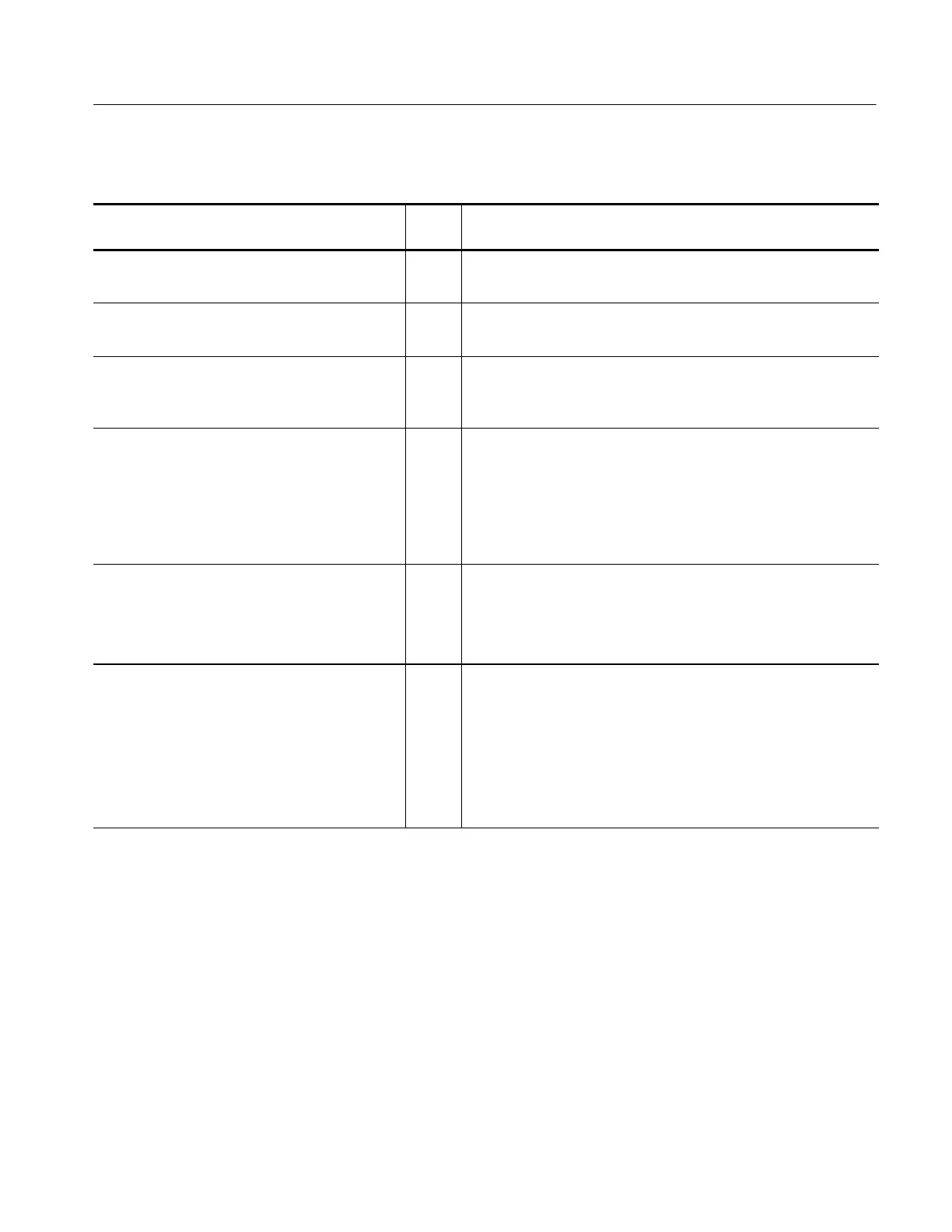
Table 6- 5: Access Instructions for Modules in Figure 6- 2
Procedure Including Module to be Removed
Page
No
Access Instructions
1 Front-Panel Knobs and Shafts 6--23 1 Do only the procedure listed at left .
2 Rem ove only the module you want to servi ce.
2 Line Fuse and Line Cord 6--26 1 Do only the procedure listed at left.
2 Rem ove only the module you want to servi ce.
3 Front Cover, Rear Cover, Cabinet, Rear EMI
Gasket, and Cabinet Handle and Feet
6--27 1DoLine Fuse and Line Cord removing only the line cord.
2 Do the procedure listed at left, removing only the module(s) you
want to service.
4 Trim Ring, Menu Elastomer, Menu Buttons,
and Front EMI Gaskets
6--31 1DoLine Fuse and Line Cord removing only the line cord.
2DoFront Cover, Rear Cover, Cabinet, Rear EMI Gasket, and
Cabinet Handle and Feet, removing only the rear cover and
cabinet.
3 Do the procedure listed at left, removing all modules including the
module(s) you want to service.
5 Disk Drive 6--34 1DoLine Fuse and Line Cord removing only the line cord.
2DotheFront Cover, Rear Cover, Cabinet, Rear EMI Gasket, and
Cabinet Handle and Feet.
3 Do the procedure listed at left to remove the module.
6 A06 Front-Panel Assembly, ESD Shield, and
Menu Flex and Probe Code Flex Circuits
6--35 1DoDisk Drive.
2DoTrim Ri ng, Menu Elastomer, Menu Buttons, and Front EMI
Gaskets.
3 Do the procedure listed at left, removing all modules including the
module(s) you want to service.
When doing the procedure list ed at left, do not remove the menu
flex circuit unless it is being replaced with a new module.

 Loading...


