Performance Tests
4-22
TDS 420A, TDS 430A & TDS 460A Service Manual
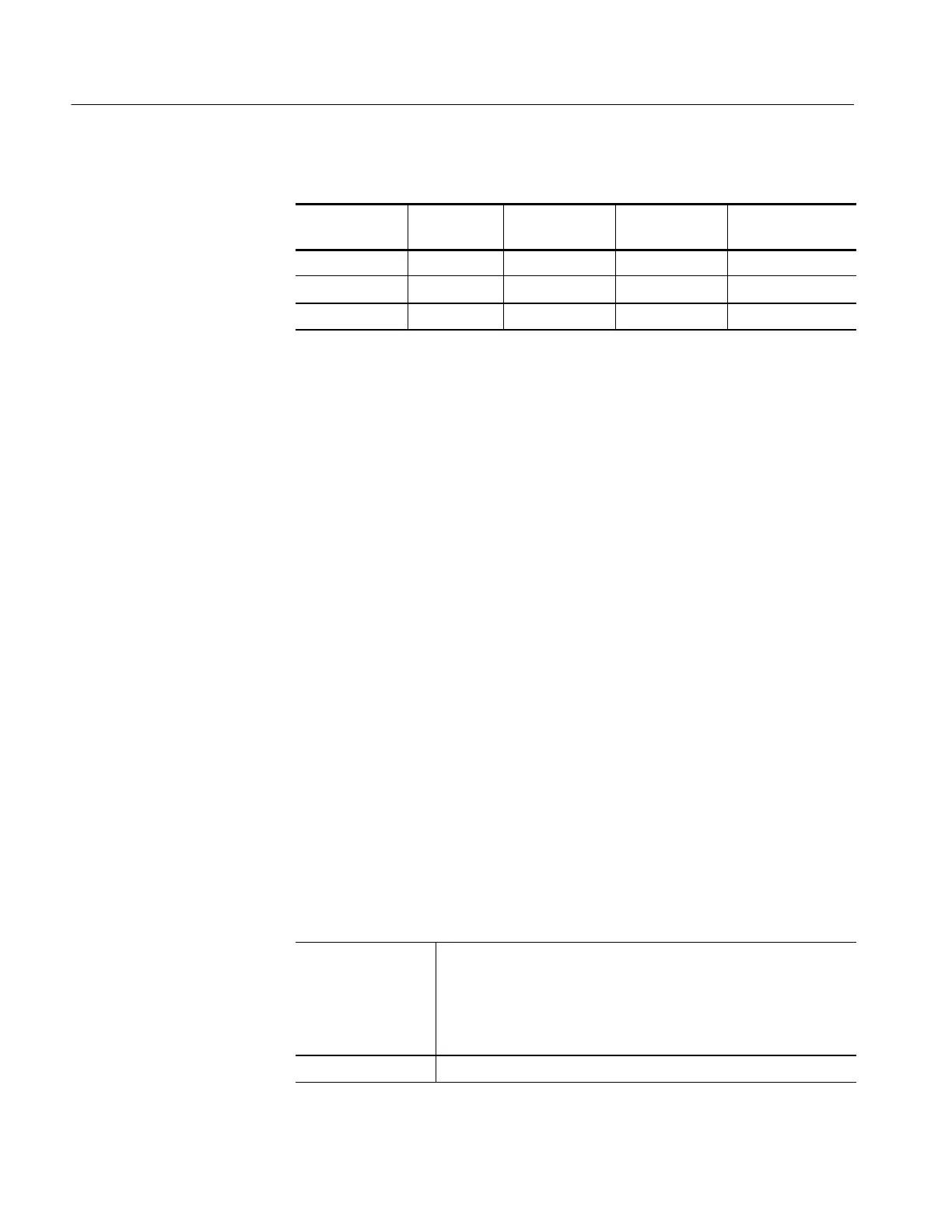
Table 4- 2: DC Offset Accur acy
Vertical
Scale Setting
Vertical
Position
Offset Setting
Generator
Setting
Offset
Accuracy Limits
1mV 0 +1 V +1 V ±5mV
100 mV 0 +10 V +10 V ±65 mV
1V 0 +99.9 V +99.9 V ±649.5 mV
b. Set the vertical scale: Set the vertical SCALE to one of the settings
listed in Table 4--2 that is not yet checked. (Start with the first
setting listed.)
c. Set the offset: Press the VERTICAL MENU button and then the Offset
main-menu button. Using the General Purpose knob, set the offset as
dictated by Table 4 --2. (Start with the first setting listed.)
d. Set the generator: Set the DC calibration generator to match the vertical
scale as dictated by Table 4--2. (Start with the first setting listed.)
e. Check against limits: Do the following subparts in the order listed.
H Subtract the measured mean from the generator setting. The result is
the offset accuracy
H CHECK that the offset accuracy is within the limits listed for the
current vertical scale setting.
H Repeat substeps b through e until all vertical scale settings listed in
Table 4--2 are checked for the channel under test.
f. Test all channels: Repeat substeps a through e for all input channels.
3. Disconnect the hookup:
a. Set the generator output to 0 V.
b. Then disconnect the cable from the generator output at the input
connector of the channel last tested.
Equipment
Required
Two dual-banana connectors (Item 7)
One BNC T connector (Item 8)
One DC calibration generator (Item 10)
Two precision coaxial cables (Item 5)
Prerequisites See page 4--15.
Check DC Voltage
Measurement Accuracy
(Averaged)

 Loading...


