Maintenance
TDS3000B Series Service Manual
6-35
6. Insert the inverter board assembly into the slots at the top and bottom of the
display chassis. The high-voltage shield end of the board is at the top of the
display. Push firmly until the tabs click.
7. Insert the display back light cable connectors into the inverter board.
Position the back light cables in the display chassis clips. See Figure 6--18.
You do not need any t ools to remove the front panel board.
Removal. Use this procedure to remove the front panel, front panel buttons, bezel
button flex circuit, and bezel buttons.
1. Place the oscilloscope face up on a soft surface (such as an anti-static mat).
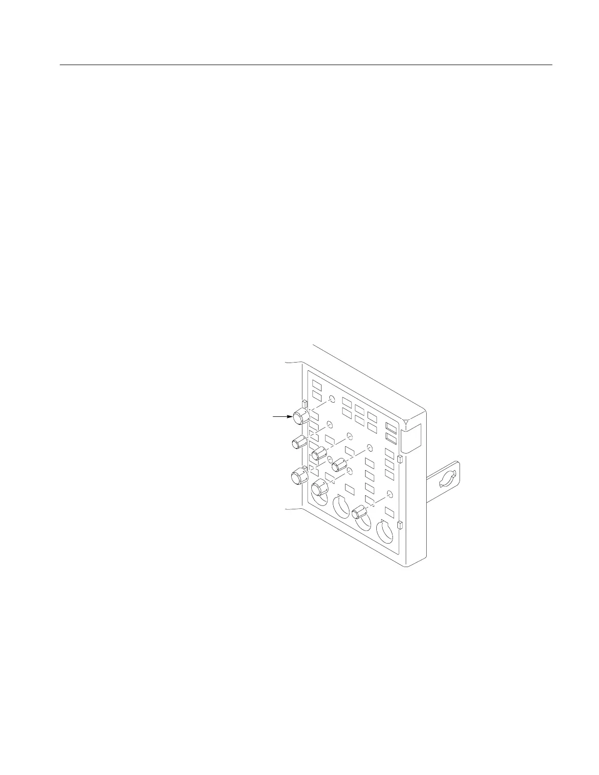
2. Remove the front-panel knobs by firmly pulling each knob away from the
front panel. Careful prying with a small screwdriver or similar tool may be
be necessary. S ee Fi gure 6--23.
Remove knobs (7)
Figure 6- 23: Remove front-panel knobs
Front Panel
 Loading...