Do you have a question about the Tektronix TDS3014B and is the answer not in the manual?
Guidelines to prevent damage to components from static discharge.
Details trigger types, sensitivity, level accuracy, and holdoff.
Steps to connect the power cord and use battery power for the oscilloscope.
How to install optional application packages to extend the oscilloscope's functionality.
Steps for installing or removing optional communication modules.
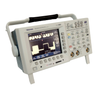
Overview of front panel buttons, controls, and how to navigate the menu system.
Procedure to adjust the probe to match the input channel for accurate measurements.
Routine to optimize the oscilloscope's signal path for maximum measurement accuracy.
Outlines the conditions and requirements before performing performance verification tests.
Instructions for running the oscilloscope's internal self-test routine.
Verifies the DC voltage measurement accuracy in average acquisition mode.
Tests the bandwidth of each channel using a leveled sine wave generator.
Assesses edge trigger sensitivity at the oscilloscope's maximum bandwidth.
Assesses edge trigger sensitivity for each channel at 50 MHz.
Verifies the accuracy of the time base by checking sample rate and delay time.
Explains the general process, prerequisites, and behavior during factory adjustments.
Describes the setup for applying DC voltage to input channels for adjustment.
Details applying AC sine wave signals to channels for calibration.
Procedures for applying fast rise step signals to all channels.
How to apply DC voltage to the external trigger input.
Step-by-step guide to performing the instrument's factory calibration process.
Precautions to prevent damage from electrostatic discharge during maintenance.
Flowcharts to help isolate and identify defective modules in the oscilloscope.
| Bandwidth | 100 MHz |
|---|---|
| Channels | 4 |
| Sample Rate | 1.25 GS/s |
| Record Length | 10, 000 points |
| Vertical Resolution | 8 bits |
| Input Coupling | AC, DC, GND |
| Power Supply | 100-240 VAC, 50/60 Hz |
| Trigger Modes | Edge, Pulse, Video, Logic |
| Interfaces | USB, GPIB, RS-232 |
| Input Impedance | 1 MΩ ± 2%, 13 pF ± 3 pF |
| Weight | 6.8 lb (3.1 kg) |