Do you have a question about the Tektronix TDS3012C and is the answer not in the manual?
Additional safety information required to safely perform service procedures on the product.
Defines terms that may appear in the manual for user understanding.
Explains symbols and terms that may appear on the product itself.
Details the electromagnetic compatibility standards and requirements the instrument complies with.
Lists the safety standards with which the product complies.
Provides information about the environmental impact of the product and end-of-life handling.
Procedures for initial verification, probe compensation, and setting time/date.
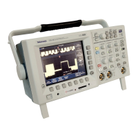
Details the oscilloscope models, features, and capabilities.
Instructions for connecting the oscilloscope to AC power or battery.
Critical safety precautions when operating the oscilloscope from battery power.
Steps for installing optional application and communication modules.
Overview of the front panel buttons and the menu system.
Details the input and output connectors located on the front panel.
Details the input and output connectors located on the rear panel.
How to display and measure signal amplitude and frequency.
Techniques for examining fine details in noisy signals.
Using FFT for spectrum analysis and detecting signal distortion.
Steps to capture transient events using single-shot acquisition.
Procedures for saving waveforms and screen images to a USB drive.
Magnifying specific parts of a waveform horizontally for detailed analysis.
Controls for managing waveform acquisition processes like Run/Stop and Single Sequence.
Controls for adjusting time base, trigger location, and examining waveform details.
Settings for configuring trigger behavior, types, and parameters.
Controls for selecting waveforms and adjusting vertical position and scale.
Details specifications for acquisition modes and sample rates.
Defines input coupling, impedance, and voltage ratings.
Details specifications for vertical controls, scale, bandwidth, and accuracy.
Details specifications for acquisition resolution, sample rate, and time base.
Lists trigger sensitivity, level accuracy, and holdoff range.
Details specifications for P6139A passive probes.
Features of optional application modules like Video, Telecom, and Analysis.
Features of the GPIB/RS-232/VGA communication module.
Information on the external battery charger and rechargeable battery pack.
General characteristics of P3010 and P6139A probes.
Procedure to match a probe to an oscilloscope input channel.
How to adjust the P3010 probe for high-frequency compensation.
Lists compatible active probes and their load factors.
General precautions for protecting the oscilloscope from damage.
Steps for cleaning the exterior of the oscilloscope.
Procedures for configuring network parameters based on DHCP/BOOTP support.
Steps to configure network printers for hard copy output.
Procedures to verify the oscilloscope's network connectivity.
Steps to resolve issues with network access and e*Scope.
| Bandwidth | 100 MHz |
|---|---|
| Channels | 2 |
| Sample Rate | 1.25 GS/s |
| Display | Color LCD |
| FFT | Yes |
| Trigger Modes | Edge, Pulse, Video |
| Interfaces | USB |
| Weight | 3.2 kg |
| Input Impedance | 1 MΩ |
| Power Supply | 100-240 V AC |