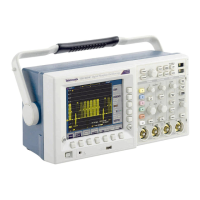
Do you have a question about the Tektronix TDS3054B and is the answer not in the manual?
Acquisition modes and stopping conditions.
Input coupling, impedance, voltage limits, and crosstalk.
Vertical scale, bandwidth, rise time, and gain accuracy.
Horizontal acquisition resolution, sample rate, and trigger.
Trigger level range, accuracy, holdoff, and video trigger.
AC line power, battery power, operating time, and charging.
Temperature, humidity, altitude, and pollution degree.
Size, weight, and drop resistance.
EMC standards met and requirements.
Safety standards and installation categories.
How to connect power cord and use battery.
Procedure to install optional application packages.
Procedure to install optional communication modules.
Using the front panel menu system and buttons.
Description of dedicated front-panel controls.
Identification of front panel I/O ports.
Identification of rear panel I/O ports.
Procedure to match probe to input channel.
Routine to optimize oscilloscope signal path.
Instructions for safely moving the instrument.
Converts AC to DC and charges the battery.
Functions related to battery interface and power distribution.
Contains acquisition, trigger, and display systems.
Microprocessor control, memory, and interfaces.
LCD, driver, and backlight components.
Microprocessor for front panel controls.
Floppy disk drive module.
Template for recording test results.
Conditions and general steps for verification.
Internal routine to verify oscilloscope functions.
Test for DC voltage measurement accuracy.
Test for bandwidth on each channel.
Test for edge trigger sensitivity at maximum bandwidth.
Test for edge trigger sensitivity at 50 MHz.
Test for time base accuracy.
List of tools and equipment for adjustments.
General steps and precautions for factory adjustments.
Equipment setups for adjustment procedures.
Steps to perform factory calibration.
Pre-service checks and safety information.
Procedures to prevent electrostatic discharge damage.
Visual inspection and cleaning of the oscilloscope.
Procedures for removing and installing major modules.
Procedure for removing and installing the oscilloscope handle.
Procedure for removing and installing the rear case.
Procedure for removing and installing the rear chassis assembly.
Procedure for removing and installing the main board.
Procedure for removing the front chassis.
Procedure for removing the display inverter board.
Procedure for removing front panel components.
Information and procedures to isolate defective modules.
Procedures for unpacking and repacking the oscilloscope.
Information needed to order replacement parts.
Options for servicing modules.
How to use the parts list.
Module-level exploded views of the oscilloscope.
| Bandwidth | 500 MHz |
|---|---|
| Channels | 4 |
| Sample Rate | 5 GS/s |
| Vertical Resolution | 8 bits |
| Display Type | Color LCD |
| Display Size | 10.4 inches |
| Input Coupling | AC, DC, GND |
| Operating Temperature | 0 °C to +50 °C |
| Record Length | 10 kpts |
| Input Impedance | 1 MΩ ± 1% in parallel with 13 pF ± 2 pF |
| Trigger Modes | Edge, Pulse, Video, Logic |
| Storage Temperature | -20°C to +60°C |


 Loading...