Maintenance
6-26
TDS3000B Series Service Manual
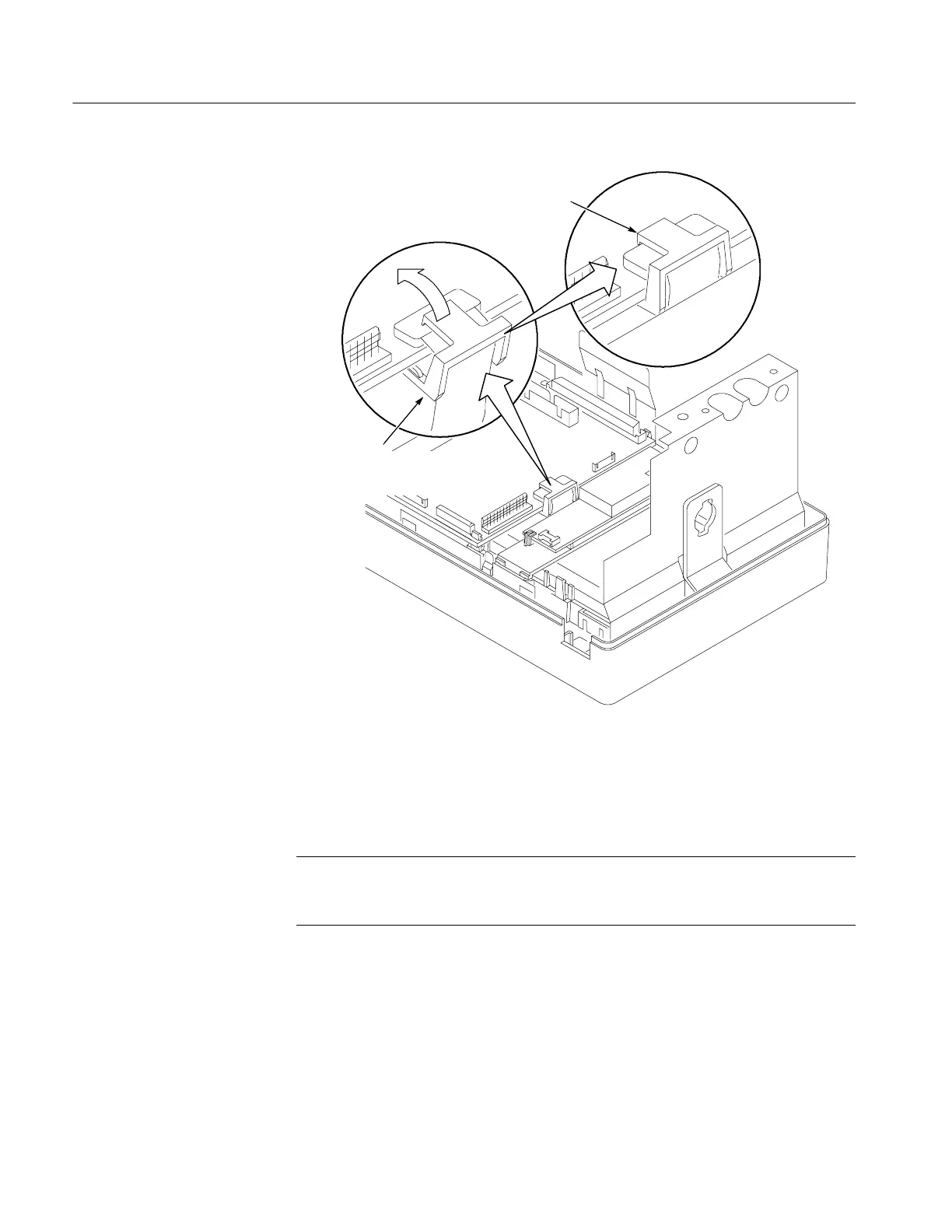
Clip sitting over
the connector
Make sure the clip legs go
under the board and do not
touch any components
Figure 6- 14: Install the J500 connector clip
6. Use a magnetic long-bit Torx® T-15 screwdriver to install the four screws
that secure the main board to the front-panel assembly.
NOTE. If after assembling the oscilloscope the display shows streaks, bars,
garbled data, or no image, open the instrument case and make sure that the
display cable is firmly and completely seated into connector J500.
7. C onnect the front-panel cable to the main board at J700.
 Loading...

