University of Portland - p. 5 of 9 - Oscilloscope - TDS3012B.docx
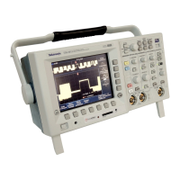
Figure 6: Vertical Position Knob Figure 7: Horizontal Position Knob
Coupling
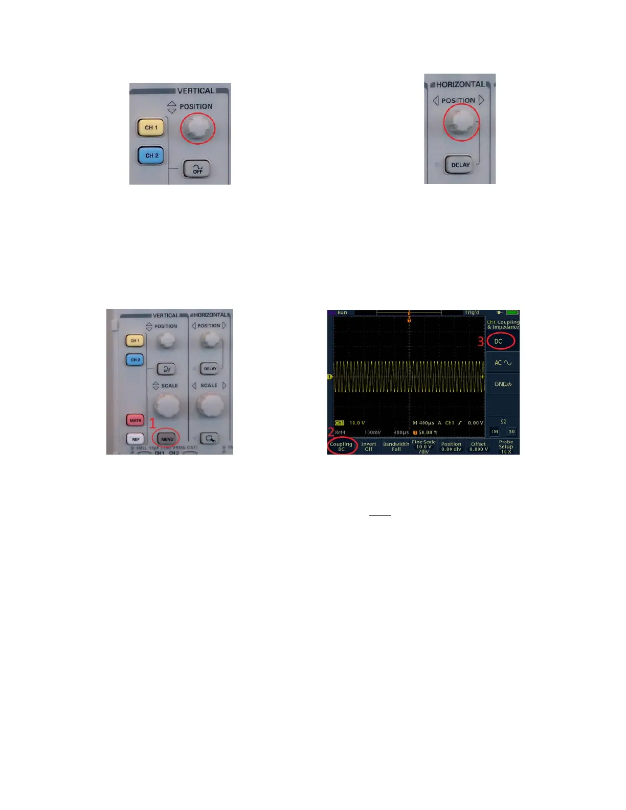
The oscilloscope has three coupling modes which determine how the signal is processed before it
is displayed. In order to select the coupling mode, press the Vertical Menu button (see Figure 8),
then press the Coupling button under the screen (Figure 9), and then select the coupling mode
with one of the buttons on the right of the screen (Figure 9).
Figure 8: Vertical Menu Button Figure 9: Coupling Button
• DC: In DC coupling mode, no processing is performed on the signal before it is
displayed, and the display represents the signal with both DC and AC parts. This is the
default mode, and is used in most cases.
• AC: The AC mode is used for signals that have a small AC signal added to a large DC
component, and you are only interested in the AC signal. This mode is often used when
testing transistor amplifiers. In AC coupling mode, the DC component is blocked, and
only the AC part of the signal is displayed. This mode allows you to expand the vertical
scale to zoom in on the small AC signal, but keep in mind that the displayed voltage is
the actual voltage minus the DC offset, NOT the actual voltage.
• GND: In ground mode, the input signal is replaced by ground, which causes the
oscilloscope to draw a line on the screen at the ground level (0 Volts). This mode is used
to check where ground is on the screen. (There is also an arrow on the left side of the
screen that marks the ground level.)
 Loading...