Adjustment Procedures
3-4
TDS3000C Series S ervice Manual
NOTE. If the DC voltage source you are using has an output head, use a
female-to-female BNC adapter and a short BNC cable to make the connection to
the first BNC tee.
A number of steps require setting the input voltage to 0.0000 V. Some calibration
equipment can inject a small amount of noise or have a very low-level AC signal
near ground. This can result in failure of the performance verification procedure
even though the instrument passes the factory adjustment procedure. If you think
that your calibration equipment injects noise or AC at zero volts, make sure to
disconnect signal cables from the oscilloscope for all steps that require 0.000 V
input.
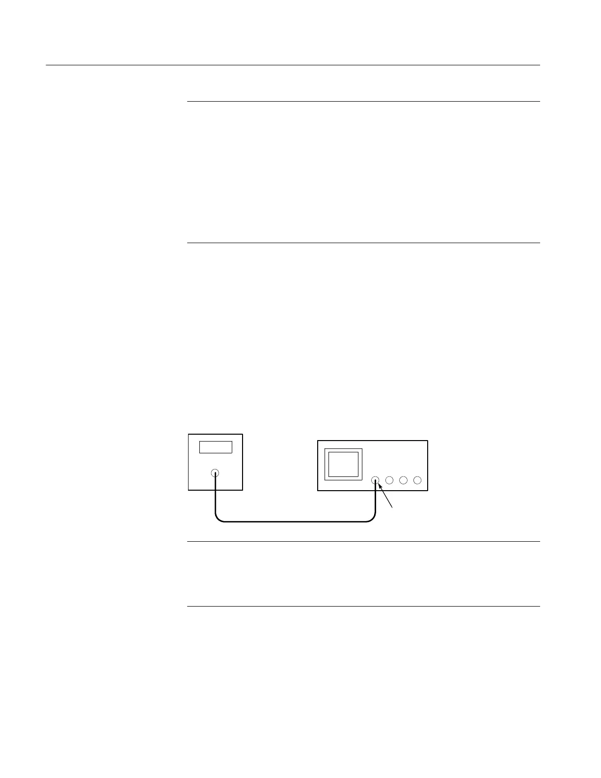
Later in the procedure, a leveled sine wave needs to be applied to each channel,
one channel at a time. A typical on-screen instruction might read:
Apply 400.00 mV Pk-Pk 80 MHz sine wave signal to
channel 1 only.
When you see an instruction similar to this, connect the leveled sine wave
generator to the specified channel and then set the amplitude and frequency to
the specified values.
Leveled sine
wave generator
Ch 1
Oscilloscope
NOTE. If the leveled sine wave generator you are using has an output head,
connect the head directly to the channel input.
Make sure that the AC generator output is set for a 50-ohm load for all
AC-source steps.
Applying AC Voltage to a
Channel
 Loading...