Getting Acquain
ted with Your Instrument
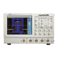
Input Connection Requirements – Options SD/HD
Use only 75 Ω coaxial cables to connect the video dev ice under test to the instrument.
Install the included 75 Ω terminations
between the end of the coaxial cables
and the instrument input channels, using
the included BNC T connectors. To
achieve accurate frequency response
measurements, it is i mportant to attach the
T c onnectors directly to the input channel
BNCs.
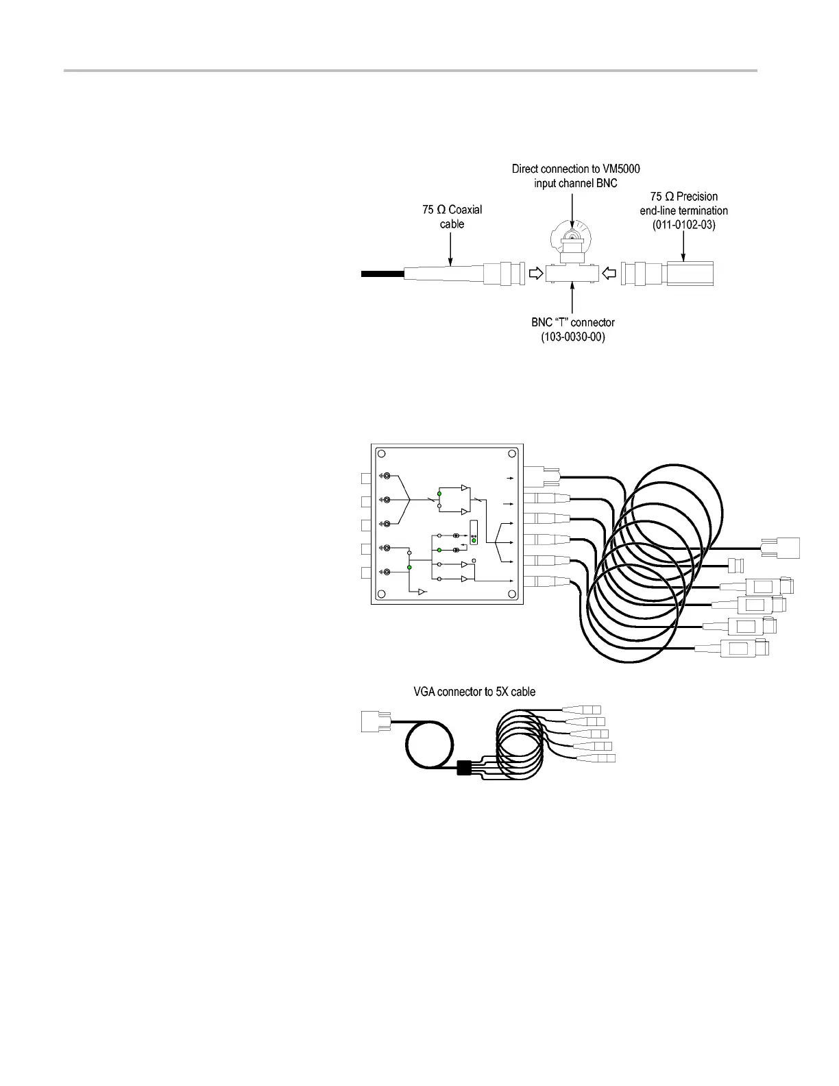
Input Connection Requirements – Option VGA
The prefe
rred method of connecting the
video device under test to the instrument is
to use the RGBHV Measurement Interface
Unit. The
Measurement Interface U nit
contains an impedance-matching circuit
to ensure accurate measurement results.
For some
measurements, a low-frequency
path is used and for other measurements
a wideband path is used. The VM Series
system s
elects which path is used through
an RS-232 connection to the Measurement
Interface Unit.
You can also connect the video device under
test to the VM Series system by using the
suppli
ed VGA connector to 5X cable. If you
use this method, you will need to connect
the cable to the VM Series system using the
suppl
ied p recision terminations and you may
need to manually change terminations while
taking measurements, depending on which
measu
rements you take.
8 VM Series Video Measurement System Quick Start User Manual

 Loading...