Performance Tests
2-46
TDS5000B Series Specifications and Performance Verification
Equipment
required
One sine wave generator (Item 13)
One 10X attenuator (Item 1)
One 50 Ω, precisi on coaxial cable (Item 4)
Prerequisites Read Prerequisites on page 2--17 and footnote warnings on page 2--19.
1. Install the test hookup and preset the instrument controls:
a. Initialize the instrument: Press the DEFAULT SETUP button.
b. Modify the default setup:
H Set the horizontal SCALE to 10 ns.
H From the toolbar, click the Vert button; then click the Termination
50 Ω button.
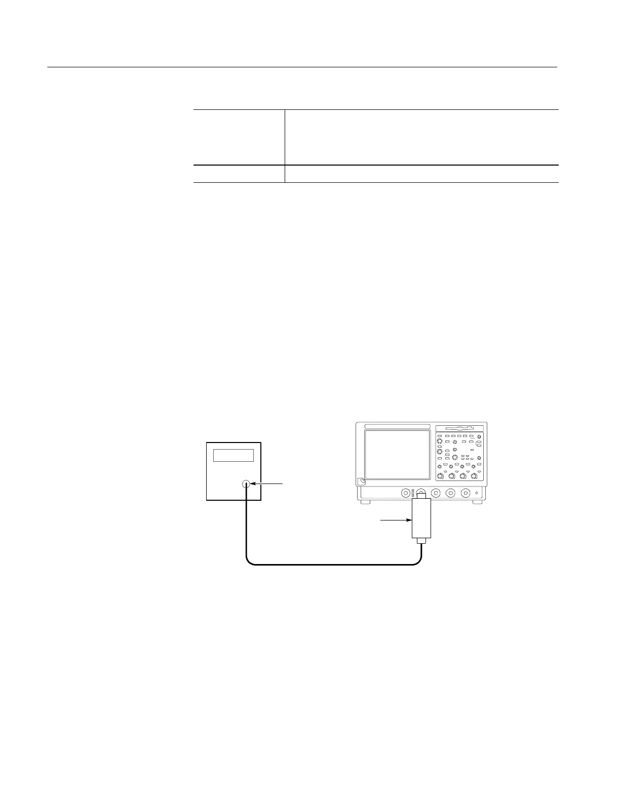
c. Hook up the test-signal source: Connect the output of the sine wave
generator (Item 13) to CH 1 as shown in Figure 2--18.
Use a 50 Ω precision coaxial cable, followed by a 10X attenuator. The
10X attenuator is optional if the SG503 is used.
TDS5000B Series oscilloscope
50 Ω coaxial cable
Sine wave generator
Output
10X Attenuator
Figure 2- 18: Initial test hookup
2. Confirm that the trigger system is within the time-accuracy limits for
pulse-glitch or pulse-width triggering (time range ≤500 ns):
a. Display the test signal: Set the output of the sine wave generator for a
100 MHz, five-division sine wave on the screen; then press PUSH TO
SET 50%.
Check Time Accuracy for
Pulse, Glitch, Timeout,
and Width Triggering
 Loading...


