Performance Tests
TDS5000B Series Specifications and Performance Verification
2-59
H Click Average and set the number of averages to 128.
2. Confirm that the Probe Compensator signal is within limits for frequency:
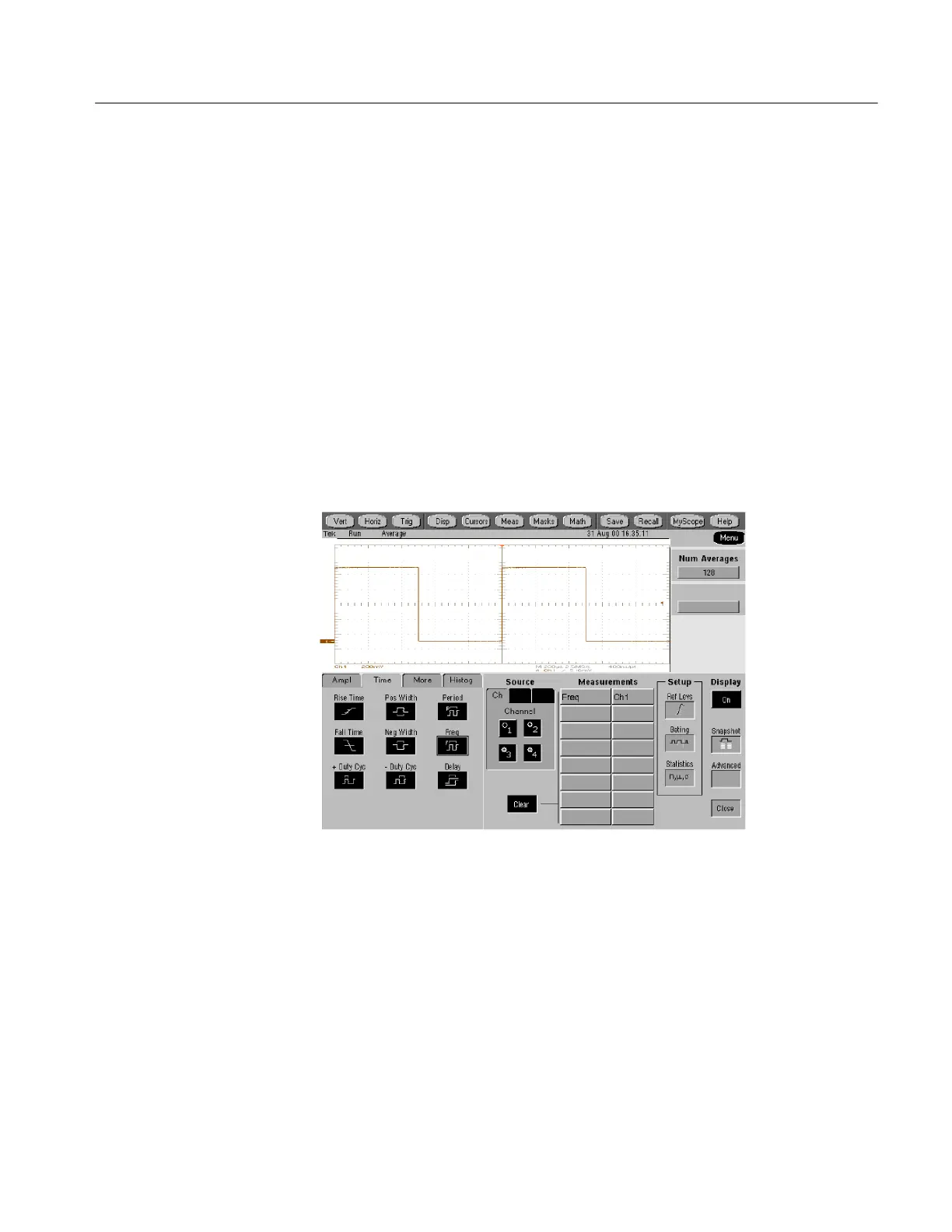
a. Measure the frequency of the probe compensation signal:
H From the toolbar, click MEAS and select the Time tab.
H Click the Freq button.
b. Check against limits:
H CHECK that the CH 1 F req readout is within 950 Hz to 1.050 kHz,
inclusive. See Figure 2--25.
H Enter the frequency in the test record.
H Click Clear to remove the measurement from the Measurements list.
Figure 2- 25: Measurement of probe compensator frequency
c. Save the probe compensation signal in reference memory:
H From the toolbar, click Save.
H In the Save What field, click Waveform.
H In the Source drop-down list box, select CH 1.
H In the Save in: Oscilloscope Memory field, select Ref 1.
H Click the Save button.
 Loading...


