Removal and Installation Procedures
6-- 42
TDS7104 & TDS7054 Service Manual
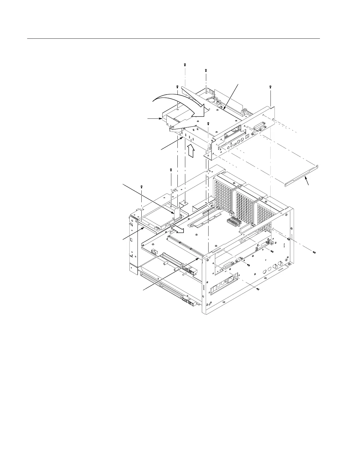
Hard/CD drive
bracket
Remove floppy
drive assembly
from front chassis
Riser adapter
board
NLX board
assembly
Place floppy drive assembly on
top of hard/CD drive bracket
Leave floppy drive
cable attached
Processor board
edge connector
Shield
Figure 6--25: NLX assembly removal
4. Remove the Riser Adapter and NLX Boards: See Figure 6--26, on page 6--44.
a. Remove the two T-15 Torx screws that secure Riser Adapter board to the
NLX support bracket.
b. Disconnect the ribbon cable connectors from the floppy drive, hard drive
and CD drive.
c. Remove the floppy drive assembly from the NLX board assembly.
 Loading...
