Specifications
TDS7104 & TDS7054 Service Manual
1-7
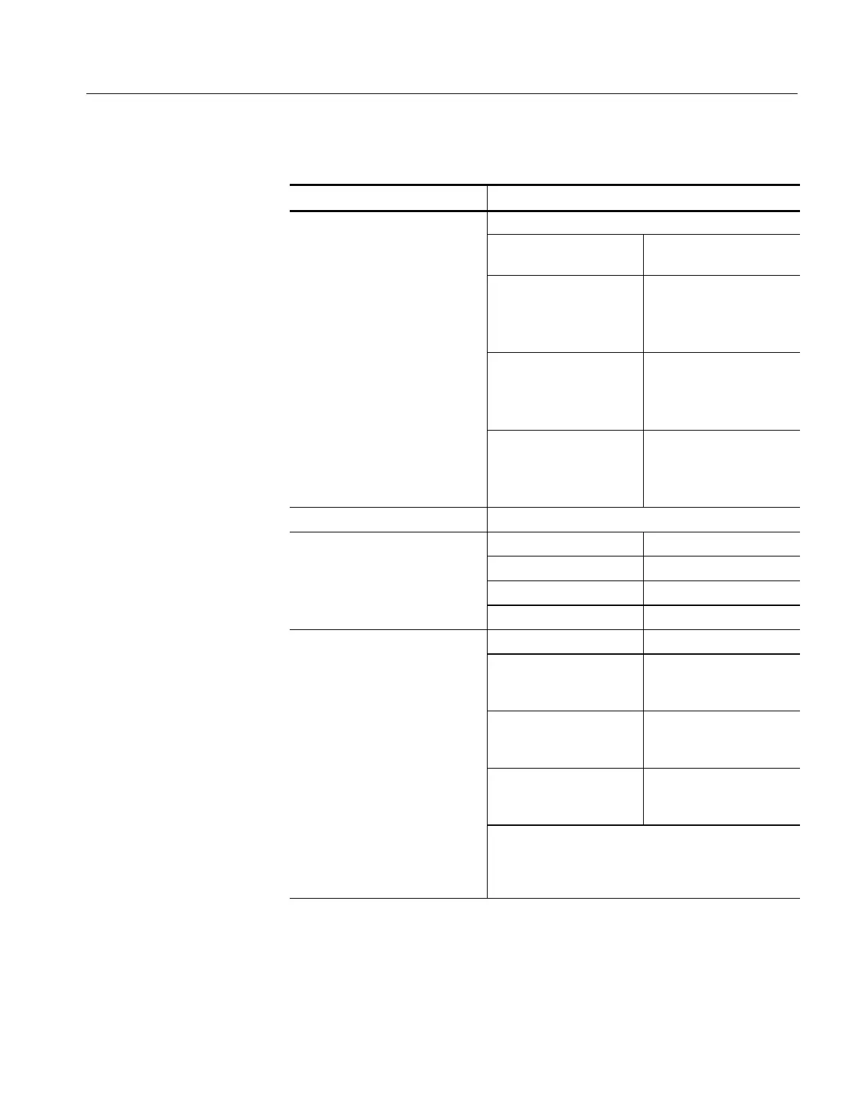
Table 1- 2: Channel input and vertical specifications (Cont.)
Characteristic Description
Step response settling errors,
Bandwidth limit set to Full
t
pi
l
SCALE range and step
amplitude
Settling error at time after
step
1 m V/div to 100 mV/div,
with ≤ 2Vstep
20 ns: ≤ 0.5%
100 ns: ≤ 0.2%
20 m s: ≤ 0.1%
101 mV/div to 1 V/div,
with ≤ 20 V step
20 ns: ≤ 1.0%
100 ns: ≤ 0.5%
20 m s: ≤ 0.2%
1.01 V/div to 10 V/div,
with ≤ 200 V step
20 ns: ≤ 1.0%
100 ns: ≤ 0.5%
20 m s: ≤ 0.2%
Position range ± 5 divisions
Offset range SCALE range Offset range
1 m V/div to 100 mV/div ±1V
101 mV/div to 1 V/div ±10 V
1.01 V/div to 10 V/div ±100 V
Offset accuracy SCALE range Offset range
1 m V/div to 100 mV/div ±(0.2% ×| net offset | +
1.5 mV + 0.1 div ×V/div
setting)
101 mV/div to 1 V/div ±(0.25% ×| net offset | +
15 m V + 0.1 div ×V/div
setting)
1.01 V/div to 10 V/div ±(0.25% ×| net offset | +
150 m V + 0.1 div ×V/div
setting)
Net offset is the nominal voltage that must be applied to
the channel to bring the trace to center screen.
Net offset = offset -- (posi tion × volts/division) and is
expressed in volts
 Loading...
