Removal and Installation Procedures
6-6
TLA5000 Series Service Manual
Equipment Required
Most parts in this logic analyzer can be removed using a screwdriver with a T-15
Torx tip.
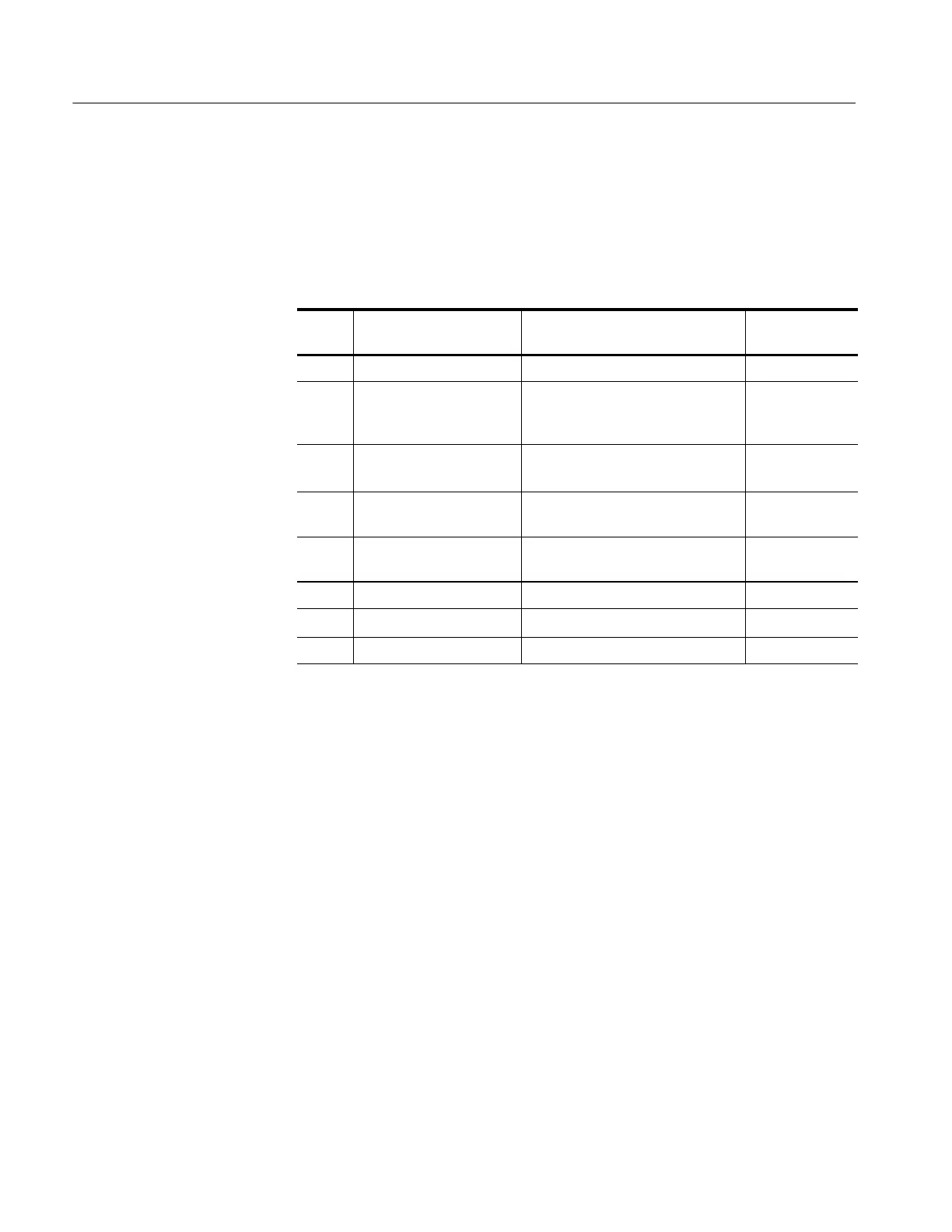
Table 6- 1: Tools required for module removal
Item
no.
Name Description
General tool
number
1 Screwdriver handle Accepts Torx-driver bits 620-440
2 T-15 Torx tip Used for removing most of t he
instrument’s screws. Torx-driver bit
for T-15 size screw heads
640-247
3
1
/
8
inch flat-bladed
screwdriver
Screwdriver for unlocking cable
connectors
Standard tool
4 #0 Phillips screwdriver Screwdriver for removing small
Phillips screws, CD, floppy drive
Standard tool
5 #1 Phillips screwdriver Screwdriver for removing small
Phillips screws, hard drive
Standard tool
6 Angle-Tip Tweezers Used to remove front panel knobs Standard tool
7
3
/
16
inch nut driver
Used to remove the nut posts Standard tool
8
9
/
16
inch open-end wrench Used to remove BNC nuts Standard tool
Accessories Pouch
You must remove the accessories pouch to access the covers on the instrument.
The remaining procedures assume that you have removed the accessories pouch.
1. Open the pouch and located the two snaps on the inside front side of the
pouch.
2. Gently pull on each of the two tabs to unsnap the front of the pouch.
3. At the rear of the instrument, peel off the Velcro that holds the pouch to the
instrument.
4. Set the pouch aside.
5. To reinstall the pouch, perform these steps in reverse order. Tighten the T-15
Torx-drive screws to 8-in lbs.
 Loading...


