10 11
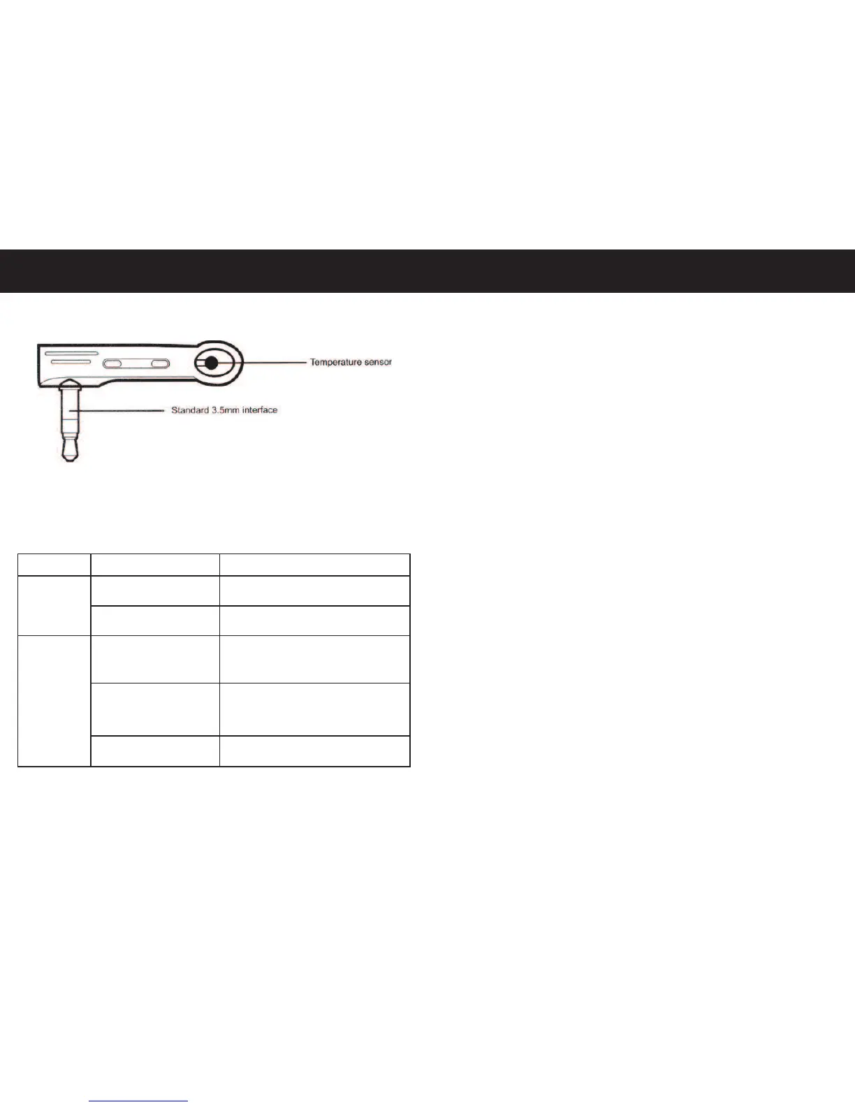
1.4. Temperature Sensor Drawing
Figure 2
1.5. LED Light Indicator (KEY)
Indicator Action Status
Power Light No Light No Mains Power Available
(Blue LED)
Constant Light Mains Power Available
GSM Light No Light NO GSM Signal / Socket
(Blue LED) Switched Off
Slow Flashing Connected to GSM Network
Light (Fading ON/OFF) / GSM Signal Available
Rapid Flashing Light
Device sending/receiving an SMS
Quick Start
2.1. Inserting the SIM card and Temperature Sensor
1. Insert the SIM into the side of the device (see figure 1), push
the SIM all the way in until it clicks (to release the SIM simply
push down on the SIM until it pops out).
2. Insert the temperature sensor into the side of the socket (see
figure 1 & 2). Note - the temperature sensor needs to be
pushed all the way in otherwise it can give inaccurate readings.
When the SIM is inserted correctly if the mobile network is
available and the device is ready to be programmed the GSM
LED Light should be fading ON/OFF (see point 1.5.).
2.2. User Authorisation Levels
All the settings in this device are controlled by SMS command
only. Powertxt® has two levels of authorisation, a master user
and an additional user. The SMS command format for additional
users is #Command#Password# (see ‘Full SMS Command List’
for additional user commands).
Master User
The master user is the first number to send Powertxt® the first
command. Only the master user has authorisation to use all the
features of Powertxt®. Only one master user number can be
programmed per socket. The master number can be changed to
another mobile number by sending an SMS command. If the
additional user changes the state of the output/power the master
user is notified by SMS.