- 15 -
GB
SPLITSPLIT
SPLITSPLIT
SPLIT 7000
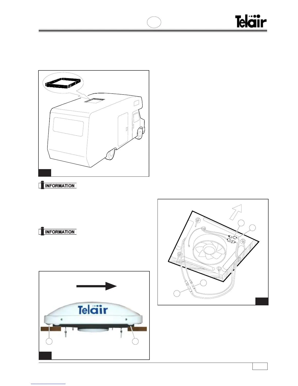
direction of the vehicle, while the rear holes Fig. 13
Ref. (2) face the rear of the vehicle.
The arrow on Fig. 13 shows the driving direction of
the vehicle.
prevent any condensate forming inside the
vehicle while the equipment is working.
Connect the two flexible hoses by screwing down
the two quick locks with their respective wrenches.
Connect the smaller hose (6 mm) Fig. 14 Ref. (3)
first, using two 19mm wrenches, and then the larger
hose (10 mm) Fig. 14 Ref. (4) with one 22mm
wrench and another 24mm wrench. Wrap the large
pipe and the coupling in the condensate-proofing
material supplied.
Introduce the aluminium air conveyor Fig. 15 Ref.
(1) into the plastic tube of the evaporator and push
it in until the 2 fastening brackets Fig. 15 Ref. (2)
are level to the roof of the vehicle, ensuring that the
4 fastening bolts pass through the fixing holes Fig.
15 Ref. (3).
Screw down the 4 nuts Fig. 15 Ref. (4) and tighten
until the thickness of the rubber liner is reduced by
1/3.
Note: The air conveyor has been designed to be
installed on vehicles with a roof thickness between
12
13
2 1
FRONT
Place the outside unit on the
roof as shown on the figure and centre it
over the 40 x 40 hole.
Connect both cables coming from the condenser
unit to the relevant cables Fig. 14 Ref. (1) and (2).
Cover the pipe with larger-
cross section (10mm) outgoing cable with the
condensate-proofing material supplied, to
14
2
1
FRONT
3
4