Chapter 3 Components and Power Supply
The following chapter provides information on the chassis of the Teldat Connect-104KF router and its components.
This information includes:
• Components.
• Information on assembly.
• Installing and removing modules.
• Power supply.
• RST button.
• Data connection.
• SIM card installation.
3.1 Components
3.1.1 Front Panel
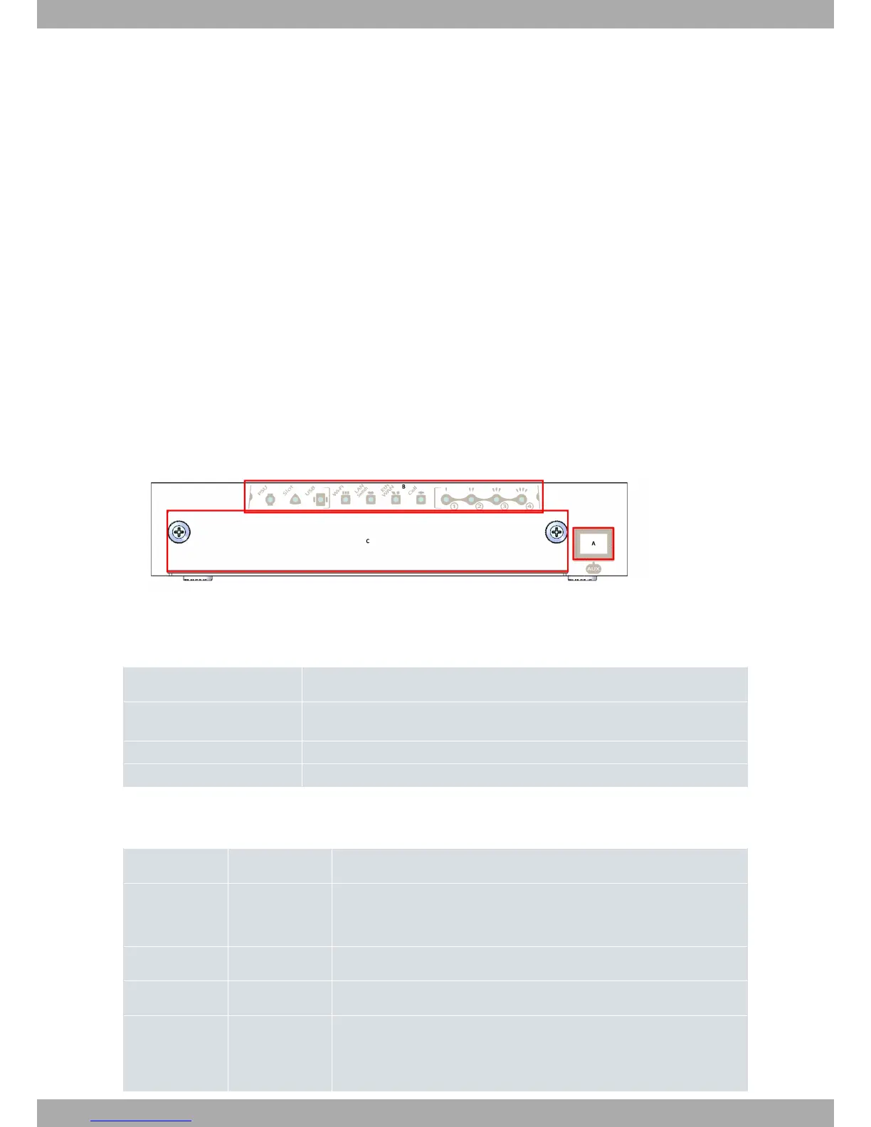
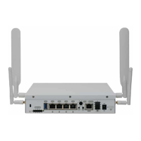
The following figure shows the front panel.
Fig. 1: Front Panel
The items on the front panel are as follows:
FRONT PANEL ELEMENTS TABLE
Item Description
A Aux. RJ45 Connector that provides access to the device’s local console for config-
uration and monitoring purposes.
B LED panel.
C Expansion card tray.
The LED panel provides information on the status of the components (whether or not they are active) or on network
activity.
LED table
LED Status Description
PSU Monochrome
green
Off -> not receiving power from PSU
On -> receiving power from PSU
Slot Tricolor This is not used on this router.
USB Tricolor This is not used on this router.
Wi-Fi Bicolor Red -> interface down
Green -> interface up
3 Components and Power Supply Teldat S.A.
4 Teldat Router Connect-104KF