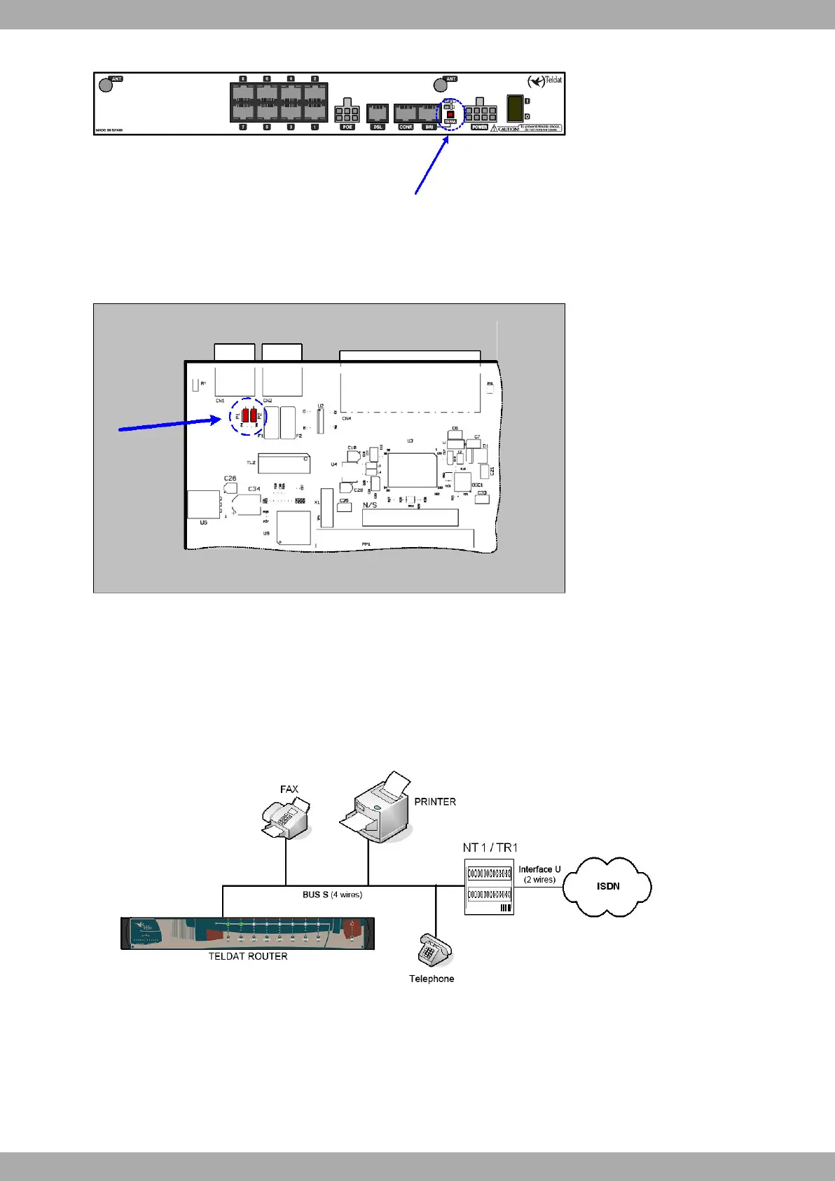
Fig. 31: Switch for the BUS-S termination resistor
The C1+ does not have a termination switch. Instead, it incorporates two internal bridges. To access these bridges,
lift the casing or the upper lid of the device. The bridges are located next to the ISDN and CONF connectors. Place
bridges P1 and P2 as shown in Figure 1.32 to activate the termination resistances:
Fig. 32: Bridges for the BUS-S terminal resistors in the C1+
The termination resistors must be placed correctly. If they aren’t, this can cause errors in data (or voice), es-
pecially if the S bus is long.
• Single or last terminal in the ISDN S bus
The TERM. pushbutton must be in the ON position if the router is the only, or the last, element connected to the
network (NT1, TR1, etc.) terminator on the ISDN S bus. By default, the device is configured in the latter position.
Fig. 33: Single or last terminal
• Intermediate position in the ISDN S bus
The TERM pushbutton must be in the OFF position if the router occupies an intermediate position in the ISDN S
bus.
Teldat S.A.
1 Installing the Router
Teldat C+ Router Family 9