EasyManua.ls Logo

Teleco TVSTRD868BST24M - User Manual

Teleco TVSTRD868BST24M
16 pages
Print Icon
To Next Page IconTo Next Page
Loading...
IT - RICEVITORE RADIO PER IL CONTROLLO DI STRIP LED 1-COLORE ANODO COMUNE
EN  RADIO RECEIVER CONTROLLING 1COLOUR LED STRIPS COMMON ANODE
FR - RECEPTEUR RADIO POUR LE CONTROLE DES LEDS MONOCHROME AVEC ANODE COMMUNE
DE  EMPFÄNGER ZUR ANSTEUERUNG VON EINFARBIGEN LED STRIPES  GEMEINSAME ANODE
IT - Codice prodotto
EN - Product code
FR - Code du produit
DE - Artikelnummer
IT - MONTAGGIO EN  MOUNTING FR - FIXATION DE  MONTAGE
165 mm
IT - Foro per il fissaggio con vite (sotto lo sportello)
EN - Hole for fixing with screw (under the cover)
FR - Trou pour fixation avec vis (sous le couvercle)
DE - Loch für die Montage mit Schraube (unter dem Deckel)
IT - Montaggio su superficie piana
EN - Flat surface mounting
FR - Fixation sur surface plate
DE - Montage auf ebene Oberfläche
70 mm
185 mm
IT - Foro per il fissaggio con vite (sotto lo sportello)
EN - Hole for fixing with screw (under the cover)
FR - Trou pour fixation avec vis (sous le couvercle)
DE - Loch für die Montage mit Schraube (unter dem Deckel)
IT - Montaggio su superficie piana
EN - Flat surface mounting
FR - Fixation sur surface plate
DE - Montage auf ebene Oberfläche
74 mm (50 mm)
56 mm
151 mm
47 mm
40 mm
TVSTRD868BST24M Master 3x4A, Box IP54 (868.3Mhz)
TVSTRD916BST24M Master 3x4A, Box IP54 (916Mhz)
LINE 230V~
LED 12 - 24V
TELECO AUTOMATION SRL
Via dell’Artigianato, 16 - 31014 Colle Umberto (TV) ITALY
TELEPHONE: ++39.0438.388511 FAX: ++39.0438.388536 - www.telecoautomation.com
This document is the property of Teleco Automation Srl who reserves all reproduction and copying rights
DOC.: T630.05_A
TVSTRDXXXBST24M
DATE:09/05/18
Question and Answer IconNeed help?

Do you have a question about the Teleco TVSTRD868BST24M and is the answer not in the manual?

Teleco TVSTRD868BST24M Specifications

General IconGeneral
BrandTeleco
ModelTVSTRD868BST24M
CategoryReceiver
LanguageEnglish

Summary

Radio Receiver Mounting

Hole for Fixing with Screw

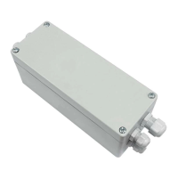
Details the screw hole location for mounting, typically found under a cover.

Flat Surface Mounting

Describes the procedure for attaching the device securely to a flat surface.

Wirings and Connections

Button Functions (ON;OFF & Dimmer)

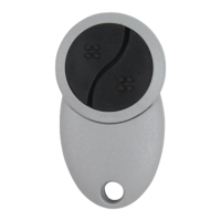
Explains how button presses (short/long) control power and dimming functions.

LED Polarity Warning

Crucial caution against inverting LED polarity to prevent damage to the diodes.

Power Supply Voltage Match

Emphasizes matching the power supply voltage to the connected LED load.

Radio Codes Memorization

Type of Memorization

Overview of different methods for programming radio transmitter codes into the receiver.

Single Button Operation

Memorization procedures using a single button for ON/OFF or Dimmer control.

3-Channel Code Memorization

Specific steps for memorizing codes for three distinct channels.

Green Mouse Code Memorization

Instructions for programming codes using the dedicated "Green Mouse" feature.

Radio Codes Deletion

Type of Deletion

Explains how to delete individual radio codes or clear all stored codes.

Single Code Removal

Step-by-step guide for erasing one specific radio code from memory.

All Codes Removal

Procedure to clear all memorized radio transmitter codes from the device.

Remote Operation Procedures

Remote Memorization of Additional Codes

How to add more radio codes remotely to the receiver system.

Remote Deletion of a Radio Code

Instructions for removing a specific radio code from the receiver remotely.

Light Intensity Memory Management

Activating;Deactivating Last Intensity Memory

Steps to enable or disable the memory function for the last light intensity setting.

Modifying Preset Light Values

Guide to adjusting pre-set brightness levels for 7/42 channel transmitters.

Safety Warnings and Compliance

General Electrical Safety Precautions

Essential warnings on power connection, polarity, insulation, and ventilation for safe operation.

EU Declaration of Conformity

Information regarding the product's compliance with EU directives and where to find the full declaration.

Technical Specifications

Power Supply and Output Ratings

Details input voltage, output current, and maximum power per output.

Operating Environment and Cabling

Specifies operating temperature range and recommended input cable cross-section.

Radio Frequency and Memory Capacity

Lists reception frequencies and the number of transmitters the radio memory can store.

Ingress Protection Rating

Indicates the device's protection level against dust and water ingress.

Related product manuals