58 www.behnke-online.de
GB
Instructions for Behnke SIP 2.0
Reset to default settings
The web interface provides a second option to
reset the door intercom to its default settings,
please see the following description of the
necessary steps to do so:
Admin
Reset
Reset
7.
reset to default settings
To reset the door intercom to its default set-
tings, please perform the following steps:
▸
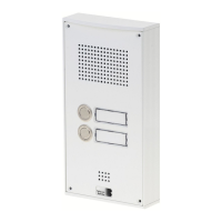
Power-off the SIP door intercom
▸
Press the buttons T1 and T2 and
keep them pressed
▸
Power-on the SIP door intercom
▸
Keep the buttons T1 and T2 pressed until the
two LEDs (green, blue) start flashing every
second
▸
Let go of buttons T1 and T2
▸
The remote station will be reset to default
settings
this process takes approx. 90 seconds
The reset is completed successfully, once you
have heard a confirmation signal from the
speaker.
 Loading...