
K
Kaylee RodriguezJul 31, 2025
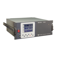
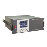
What to do if Teledyne 7500 shows Error No. 6?
- CChelsea TaylorJul 31, 2025
If Teledyne Analytical Instruments displays Error No. 6, it could be due to several reasons. First, check if the span gas is being supplied properly. Next, verify that the calibrated concentration setting matches the cylinder concentration; if not, adjust it accordingly. Ensure that zero calibration was performed correctly. A dirty cell can also cause span deflection, so cleaning the cell might resolve the issue. Lastly, if the detector sensitivity has deteriorated, consider testing and replacing the detector.