Do you have a question about the Teledyne 7500 and is the answer not in the manual?
Pinout and signal names for the CN2 communication connector.
Instructions for connecting the instrument using an RS-232 reverse cable.
Lists parameters like transmission speed, data length, stop bits, and station number.
Guides setting the station number via the analyzer's maintenance mode.
Details Modbus message components: Station No., Function Code, Data, CRC.
Describes slave station responses to commands and error code definitions.
Details Modbus function codes and their correspondence to register addresses.
Step-by-step guide for calculating the CRC-16 error check code.
Outlines timing requirements for master and slave communication.
How to calculate exact values using decimal point and unit data.
Register address map for user settings like calibration parameters.
Lists user settings for auto calibration, alarm settings, and range switches.
| Brand | Teledyne |
|---|---|
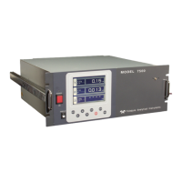
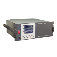
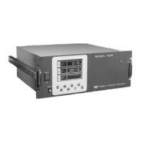
| Model | 7500 |
| Category | Analytical Instruments |
| Language | English |