April 2018 Pathfinder DVL Guide
Page 36
EAR-Controlled Technology Subject to Restrictions Contained on the Cover Page.
Mechanical Integration Considerations
Alignment
The mechanical alignment of the transducer head is important to DVL data accuracy. Mechanically mount
the head as close as possible to your reference point. This is usually with the Beam 3 mark at 0° or 45° rel-
ative to the ship’s fore-to-aft centerline. You also must mount the transducer head as level as possible us-
ing the ship’s roll and pitch references.
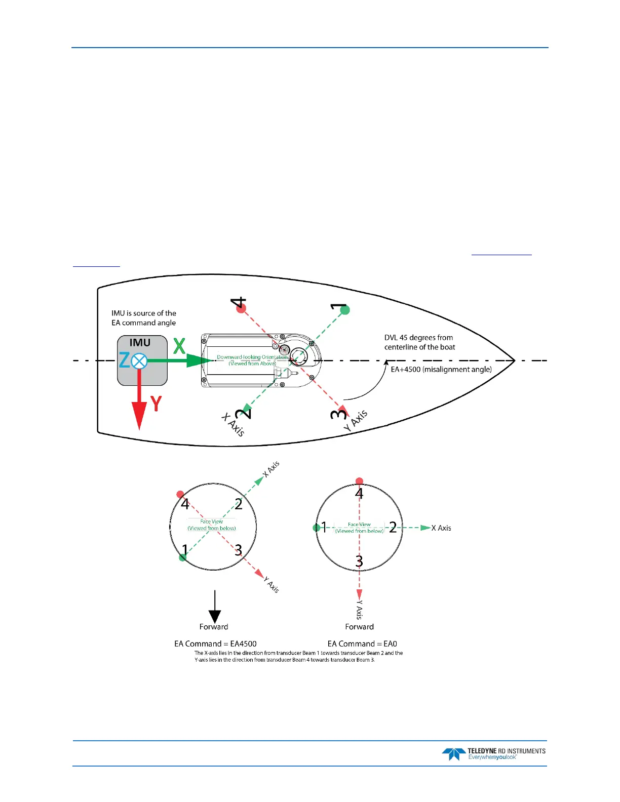
TRDI recommends mounting the transducer head with Beam 3 (instrument Y-axis) rotated 45° relative to
the ship forward axis (Figure 20). This causes the magnitude of the signal in each beam to be about the
same. This improves error rejection, reduces the effect of ringing, and increases the Pathfinder’s effective
velocity range by a factor of 1.4. If Beam 3 is aligned at an angle other than zero, use the EA command to
describe the rotation between instrument Y axis (beam 3) and ship forward axis. Refer to EA - Heading
Alignment.
Figure 20. Transducer Alignment Reference Points
 Loading...