System Configuration (Cont.)
System Configuration
2 RDR-1600 Pilot’s Guide TM106101(8/01) TM106101(8/01) RDR-1600 Pilot’s Guide
2.0SYSTEM CONFIGURATION
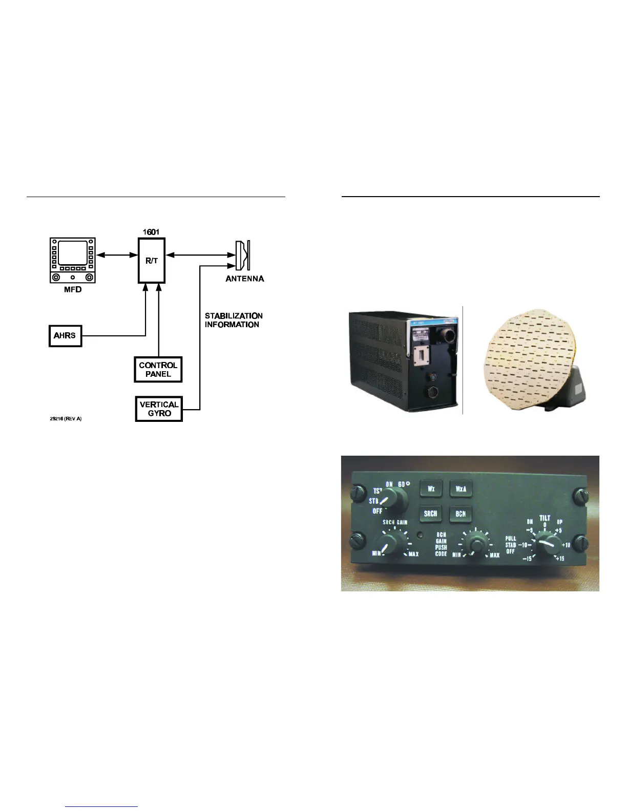
Figure 2-1.Typical System Block Diagram
2.1ANTENNA AND RECEIVER-TRANSMITTER
The RT-1601 Receiver-Transmitter generates 10 KW pulses of X-band
energy. Reflected signals of weather, search and beacon modes received
by the antenna are amplified and sent to the radar display indicator.
The flat-panel antenna, which is available in diameters of 10, 12 or 18
inches scans 60 or 120 degrees. Swept by a motor-driven gear train, the
vertical component is positioned by the tilt control on the Radar Control
Panel (RCP or CP-113k). A stabilization system presents an upright radar
display while the aircraft is turning, climbing or descending.
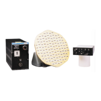
Figure 2.1-1.Receiver-
Transmitter
Figure 2.1-2.DA-1203A Drive
Assembly with AA4512A 12” Flat
Plate Antenna
Figure 2.1-3.CP-113K Control Panel