Home
Telephonics
Intercom System
Trulink
Page 12 (Figure 1.6-1. Trulink Components)
Telephonics Trulink - Figure 1.6-1. Trulink Components
59 pages
Manual
Save Page as PDF
To Next Page
To Next Page
To Previous Page
To Previous Page
Loading...
T
ELEPHONICS
C
ORPORATION
TM115007 REV A (04/07)
1-4
USE OR DISCLOSUR
E OF DATA CONTAIN
ED ON THIS PAGE
IS SUBJECT TO THE
RESTRICTION
ON THE TITLE PA
GE OF THIS DOCUM
ENT
.
C
OMMUNICATION
S
YSTEMS
D
IVISION
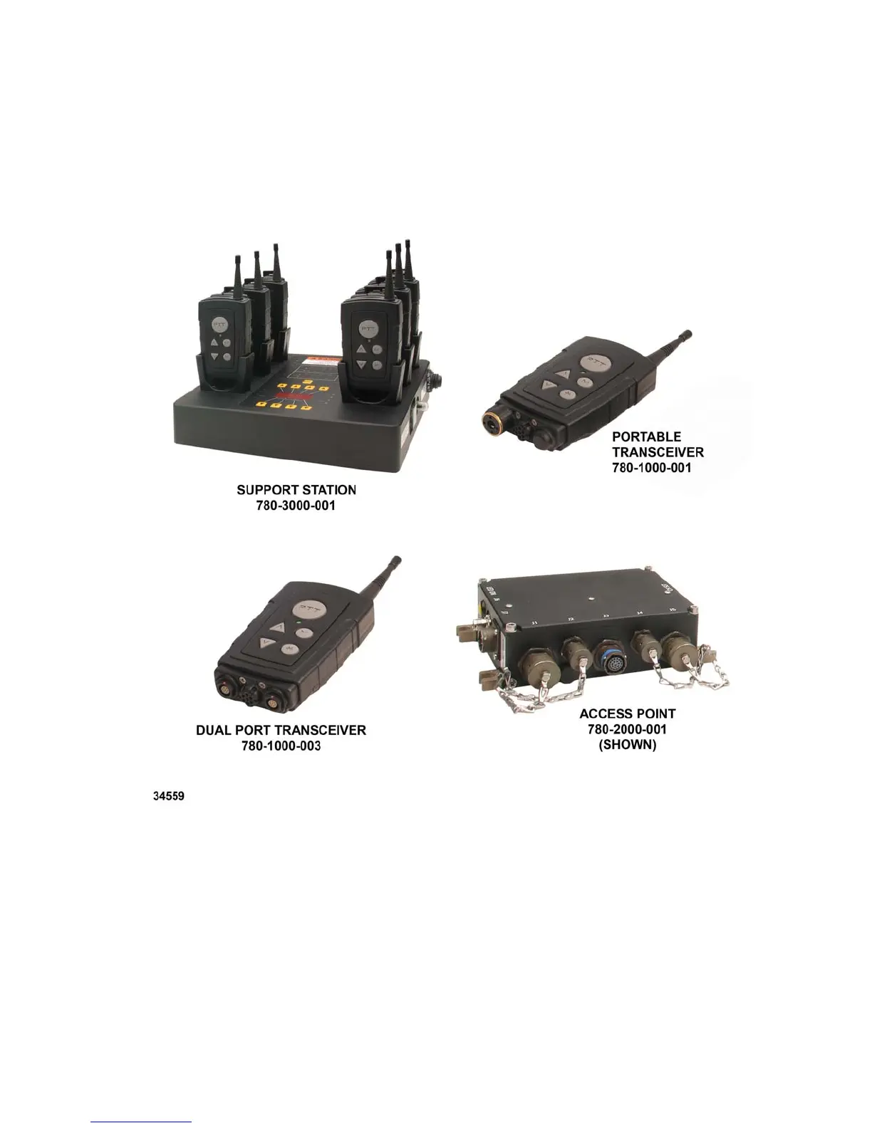
Figure 1.6-1. TruLink Components
11
13
Table of Contents
Main Page
Default Chapter
6
Table of Contents
6
Chapter 1 General Description
9
Introduction
9
Definitions and Abbreviations
9
Definitions of Terms Used
9
Abbreviations and Acronyms
9
Trulink Description
10
Network Configuration
10
Capabilities
10
Trulink Equipment
11
Table 1.6.1 Trulink Equipment List
11
Figure 1.6-1. Trulink Components
12
Chapter 2 Operation
13
Overview
13
Physical Description
13
Batteries
13
Installing/Changing
13
Battery Type
14
Figure 2.3.2-1. Trulink Portable Transceiver (TPT)
14
Low Battery Warning
15
Charging the TPT
15
Figure 2.3.4-1. TPT Unit Dimensions (Inches)
16
Figure 2.3.4-2. Battery Installation
17
Antenna
18
Headset
18
Tpt Status and Indicators
18
Visual Indicators
18
Table 2.6.1-1 LED Indications
19
Audible Indicators
21
Synvoice Phrases
21
Table 2.6.2-1 Audio Indications
21
Table 2.3.6-1 Summary of Available Synvoice Phrases (Configuration-Dependant)
22
Tpt Operation
23
Introduction to TPT Man-Machine Interface
23
Power ON/OFF
23
Start-Up
23
Starting a Network
24
Logging on to a Network
24
Settings
25
CHANNEL Setting for TPT
25
VOX Setting
26
KEY LOCK Setting
26
LED Setting
26
ORDER CHANGE MASTER Setting
27
ORDER SYNCHRONIZE ACCESS POINT Setting (Changing TAP Channel)
27
Talking on the Network
28
Transmission Rejection
28
Transmission Indication
28
Volume Adjustment
28
Out of Range
28
Key-Click
29
Power-On BIT Failure
29
Tpt Check out Procedure
29
Chapter 3 Trulink Access Point
30
Overview
30
Figure 3.1-1. TPT and TAP Network
30
Physical Description
31
Tap Installation
31
Mounting
31
Figure 3.3.1-1. TAP Unit Dimensions (Inches)
31
Connections
32
Power Connector
32
Antenna Connector
32
Audio Connectors
32
Figure 3.1.1-2. TAP Controls and Connectors
32
Data Connectors
33
Tap Operation
33
Power ON/OFF
33
Echo Elimination Procedure
33
ORDER SYNCHRONIZE ACCESS POINT Setting (Change TAP Channels)
34
ORDER CHANGE MASTER Setting
34
Logging on to a Network
35
Status Indications
35
Power-On BIT Failure
35
Table 3.4.6-1 Status LED Indications
35
Tap Check out Procedure
36
Chapter 4 Trulink Dual Port Transceiver
37
Overview
37
Figure 4.1-1. Dual Port Transceiver
37
Physical Description
38
Operation
38
Figure 4.2-1. Dual Port Transceiver (DPT) Unit Dimensions
38
ICS Interface
39
Logging on to a Network
39
Dual Port Transceiver Check out Procedure
40
Chapter 5 Trulink Support Station
41
Overview
41
Physical Characteristics
41
Figure 5.2-1. TSS Controls and Indicator
41
Charge Indication
42
Figure 5.2-2. TSS Display Overlay
42
Table
42
Bit Indication
43
Tpt Channel Selection
43
Table 5.3-1 Charge LED Indication
43
Table 5.4-1 BIT LED Indications
43
Tss Check out Procedure
44