T ELEPHONICS C ORPORATION
TM115007 REV A (04/07) 3-3
USE OR DISCLOSURE OF DATA CONTAINED ON THIS PAGE IS SUBJECT TO THE
RESTRICTION ON THE TITLE PAGE OF THIS DOCUMENT.
C
OMMUNICATION S YSTEMS D IVISION
LED
(Not seen)
Channel Set
Button
Not seen
udio
Connectors
Power
Connector
Status
LE
(Not seen)
ntenna
Connector
Data
Connectors
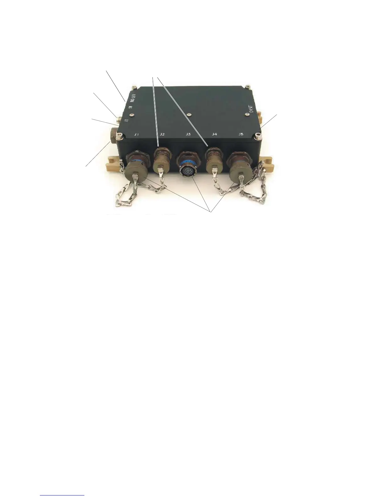
Figure 3.1.1-2. TAP Controls and Connectors
3.3.2 Connections
3.3.2.1 Power Connector
The power connector is marked J7. The vehicle DC power source must be supplied through a 1 Amp
fuse or circuit breaker (not supplied).
3.3.2.2 Antenna Connector
The antenna connector is marked J6. The antenna connected to the TAP is chosen according to the
physical installation (vehicle, vessel or aircraft) and connects via a TNC-male with 50-Ohm
impedance. The standard antenna provided can be directly mounted to the TAP, or remotely
mounted not more than ten feet away via a cable (not supplied). The antenna must be located so that
there is a clear (RF) path between it and the users. The antenna cannot be located within a metal
enclosure.
3.3.2.3 Audio Connectors
The three audio connectors are marked J1, J3 and J5. The connectors are identical except that each is
keyed to mate with only one cable. Each connector has provisions for line level audio input and
output, both 600 Ohms. Additionally, a floating PTT discrete output is available. Both PTT wires
must be connected for proper operation. The low PTT line should be connected to the intercom
return.
Data
Connectors
Status
LED
(Not Seen)
LED Button
(Not Seen)