T ELEPHONICS C ORPORATION
TM115007 REV A (04/07) 3-2
USE OR DISCLOSURE OF DATA CONTAINED ON THIS PAGE IS SUBJECT TO THE
RESTRICTION ON THE TITLE PAGE OF THIS DOCUMENT.
C
OMMUNICATION S YSTEMS D IVISION
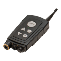
3.2 PHYSICAL DESCRIPTION
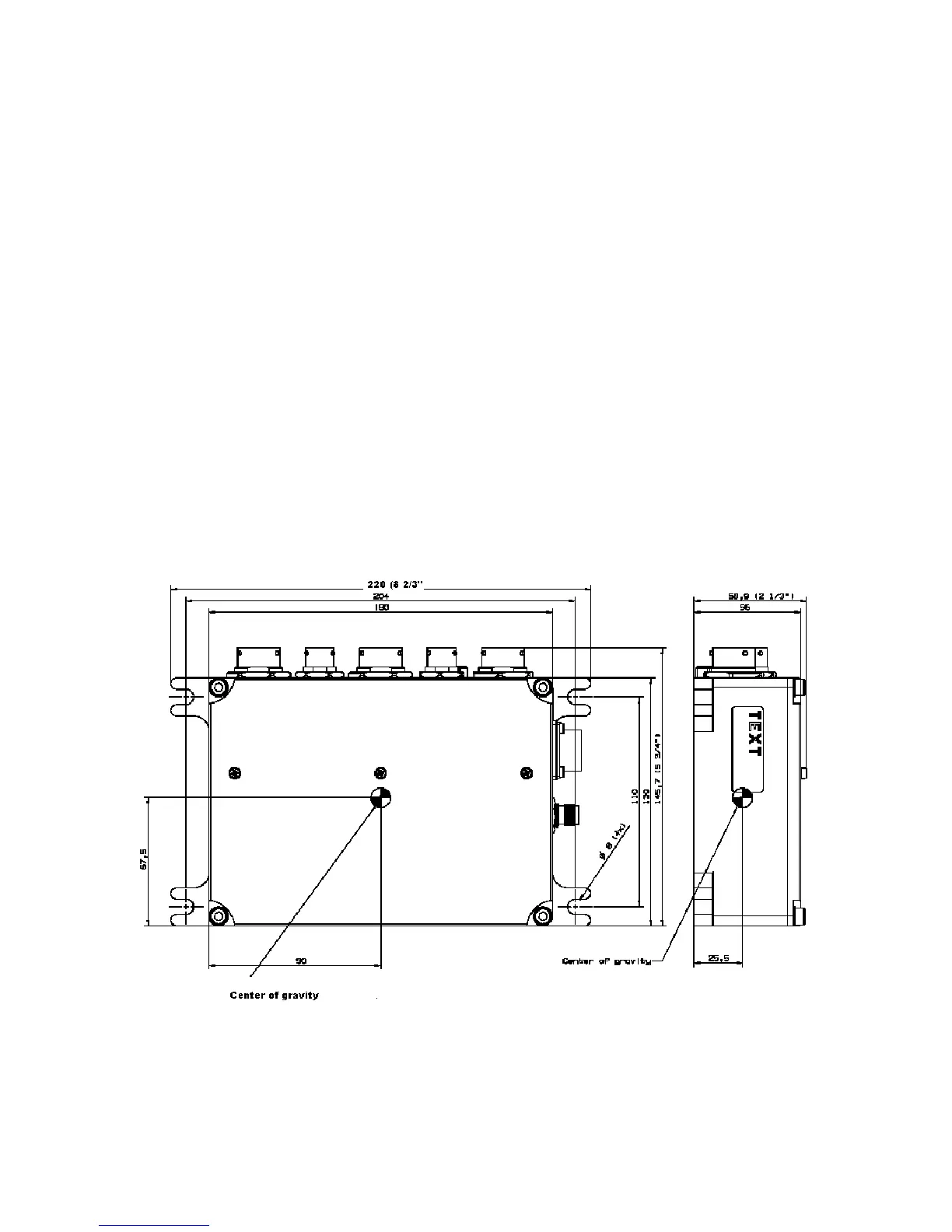
The TAP is powered by DC power from the host vehicle. It measures 8.7 inches in length by 5.7
inches wide by 2.3 inches high. It weighs approximately 2.9lbs. The physical characteristics are
shown in Figure 3.3.1-1.
The TAP has connectors for power, antenna, audio and data. There are also two pushbuttons, one for
setting the channel and one to operate the status LED. See Figure 3.3.1-2 for a picture of the TAP
controls, indicator and connectors.
3.3 TAP INSTALLATION
3.3.1 Mounting
The TAP has four flanges for bolting the unit into the host vehicle. The flanges are bare metal to
facilitate connection to ground. The mounting surface should be cleaned to bare metal to ensure a
good chassis ground.
It is recommended that the TAP be located near the data and audio devices to avoid long lengths of
cabling. The unit also needs to be accessible by the operator for channel selection and to view the
LED status indicator.
Figure 3.3.1-1. TAP Unit Dimensions (Inches)